HVAC / Compressor Controllers
Installation and Wiring Guide for Secop 105N496x Series Controller
Quick installation and wiring guide for Secop 105N496x Series controllers. Includes connection diagrams, airflow requirements, brazing precautions, and technical specifications.
Table of contents
Manual images
Click an image to enlargeQuick Guide from the Manual
The Secop 105N496x Series controller is designed for use with NLV compressors. This document provides essential wiring, installation, and service information. Ensure all electrical connections are made according to the provided wiring diagram and that the unit is operated within the specified environmental and electrical limits.
Wiring and Connections
The controller supports various connection types including RAST 5, RAST 2.5, and Spade connectors (6.3 x 0.8). The wiring diagram details the following connections:
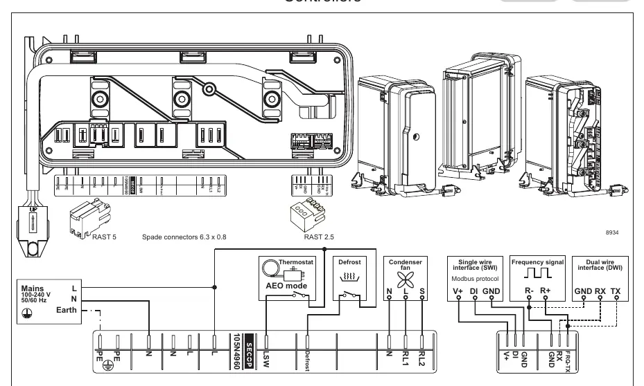
- Mains: 100-240 V, 50/60 Hz (L, N, Earth/PE).
- Control Inputs: Thermostat, Defrost, and AEO mode.
- Outputs: Condenser fan, RL1, and RL2.
- Communication Interfaces: Supports Modbus protocol (Single wire interface), Frequency signal, and Dual wire interface (DWI).
Service and Repair
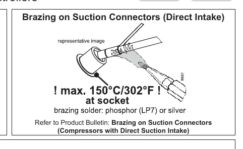
When performing service or repair on systems using R290 refrigerant, adhere to strict safety protocols. When brazing on suction connectors (Direct Intake), do not exceed a maximum temperature of 150°C (302°F) at the socket. Use phosphor (LP7) or silver brazing solder. Refer to the specific Product Bulletin for detailed instructions on brazing compressors with direct suction intake.
Installation Requirements
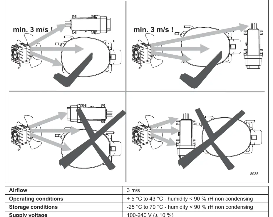
Proper airflow is critical for the operation of the compressor and controller. Ensure a minimum airflow of 3 m/s is maintained across the unit. Refer to the installation diagrams for correct fan positioning to ensure adequate cooling.
Technical Specifications
- Supply voltage: 100-240 V (± 10 %)
- Frequency: 50/60 Hz
- Input power, max: 1000 W
- Operating conditions: + 5 °C to 43 °C, humidity < 90 % rH (non-condensing)
- Storage conditions: -25 °C to 70 °C, humidity < 90 % rH (non-condensing)
Practical help
Common problems
Overheating or thermal shutdown
Ensure minimum airflow of 3 m/s is maintained across the compressor and controller.
Damage during brazing
Do not exceed 150°C (302°F) at the socket when brazing suction connectors.
Before use
- Verify supply voltage is within 100-240 V (± 10 %).
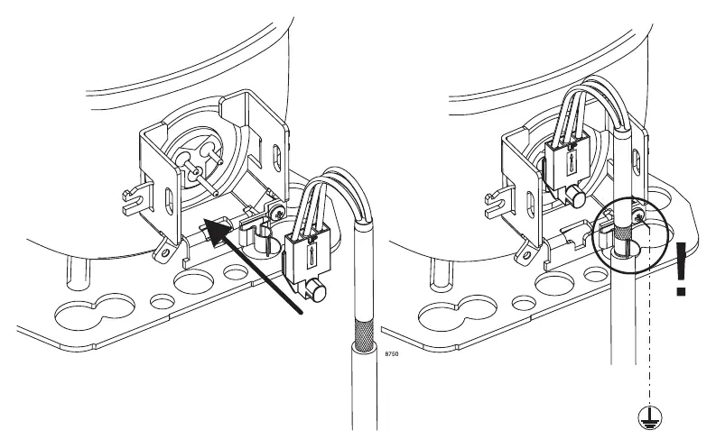
- Ensure proper grounding (Earth/PE connection) is established.
- Check that the fan provides a minimum airflow of 3 m/s.
- Confirm the correct connector types (RAST 5, RAST 2.5, or Spade) are used for your specific setup.
- Ensure operating environment is between +5°C and +43°C.
Specs in practice
- Supply voltage
- 100-240 V (± 10 %) AC input range.
- Input power, max
- Maximum power consumption of 1000 W.
Images and diagrams
- The wiring diagram illustrates connections for Mains, Thermostat, Defrost, and Condenser fan.
- Interface options include Modbus (Single wire), Frequency signal, and Dual wire interface (DWI).
- Grounding instructions show the correct connection point for the Earth/PE wire.
Model compatibility
- Compatible with R290 refrigerant systems.
- Supports multiple communication protocols: Modbus, Frequency signal, and Dual wire interface.

Manual page author
Emily Carter
User documentation editor
Prepares concise manual descriptions and highlights the most useful setup, operation, and maintenance information for readers.