HVAC / Compressor Controllers
Secop DLV Compressor Controller 105N446x User Manual
Quick guide for the Secop DLV 105N446x series compressor controller. Includes wiring diagrams, technical specifications, installation requirements, and safety precautions for R290 systems.
Table of contents
Manual images
Click an image to enlargeQuick guide from the manual
This document provides essential instructions for the Secop DLV 105N446x series compressor controllers. Users must adhere to the specified voltage, airflow requirements, and safety protocols, particularly when working with R290 refrigerant systems. Always refer to the provided wiring diagram for correct electrical connections.
Wiring and connections
The controller requires precise wiring to function correctly. The system supports connections for Mains (115V AC), Thermostat, Defrost, Frequency/DWI signal, Serial communication, and the DLV Compressor.
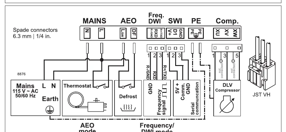
- Mains: Connect to L and N terminals.
- DLV Compressor: Connect to pins 1, 3, and 5.
- Frequency/DWI: Connect to the designated Frequency signal and GND terminals.
- Serial Communication: Connect to the 5V+, Comm, and GND terminals.
Ensure all spade connectors (6.3 mm / 1/4 in) are securely attached according to the wiring diagram provided in the manual.
Installation and safety
Proper installation is critical for the longevity and safety of the compressor system.
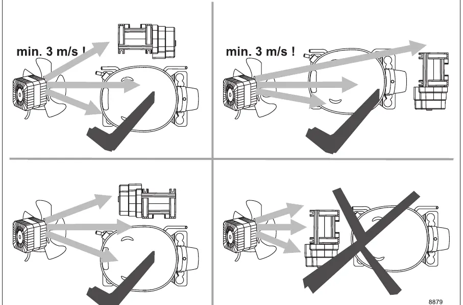
- Airflow: A minimum airflow of 3 m/s is required for the compressor. Ensure the installation environment allows for adequate ventilation.
- Service/Repair (R290): When performing maintenance on systems using R290 refrigerant, exercise extreme caution due to flammability.
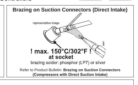
- Brazing: When brazing on suction connectors (Direct Intake), do not exceed a temperature of 150°C (302°F) at the socket. Use phosphor (LP7) or silver brazing solder.
Technical specifications
The following specifications apply to the 105N446x series controllers:
- Supply voltage: 100-127 V (± 10%)
- Frequency: 50/60 Hz
- Input power rating: 450 W
- Operating conditions: +5°C to 43°C, humidity < 90% rH (non-condensing)
- Storage conditions: -25°C to 70°C, humidity < 90% rH (non-condensing)
Practical help
Common problems
Overheating during brazing
Do not exceed 150°C/302°F at the socket when brazing on suction connectors.
Insufficient cooling performance
Ensure the compressor has a minimum airflow of 3 m/s.
Before use
- Verify supply voltage is 100-127V 50/60Hz.
- Ensure ambient temperature is between +5°C and 43°C.
- Check that humidity is below 90% rH (non-condensing).
- Confirm wiring matches the provided diagram for Mains, Thermostat, and Compressor.
- Ensure proper ventilation is available (min 3 m/s airflow).
Specs in practice
- Supply voltage
- 100-127 V (± 10%)
- Input power rating
- 450 W
- Operating temperature
- +5°C to 43°C
Images and diagrams
- The wiring diagram illustrates the connections for Mains, Thermostat, Defrost, Frequency/DWI signal, Serial communication, and the DLV Compressor.
- Connector pins 1, 3, and 5 are specifically for the DLV Compressor connection.
Model compatibility
- Designed for DLV Compressors.
- Requires specific brazing precautions for R290 systems.

Manual page author
Michael Turner
Technical manual editor
Reviews PDF manuals for structure, safety notes, and practical product details so readers can find the right information quickly.