HVAC / Compressor Controllers
Secop NLV Compressor Controller Instructions
Quick guide for Secop NLV compressor controllers (105N4962, 105N4966, 105N4972). Includes wiring diagrams, airflow requirements, and operating conditions.
Table of contents
Manual images
Click an image to enlargeQuick guide for Secop NLV controllers
This document provides installation and wiring instructions for Secop NLV compressor controllers, specifically models 105N4962, 105N4966, and 105N4972. It covers electrical connections, airflow requirements, and safety precautions for service and repair.
Wiring and connections
The controller supports various configurations including mains power, thermostat, defrost, condenser fan, and communication interfaces. Ensure all connections are made according to the provided wiring diagram:
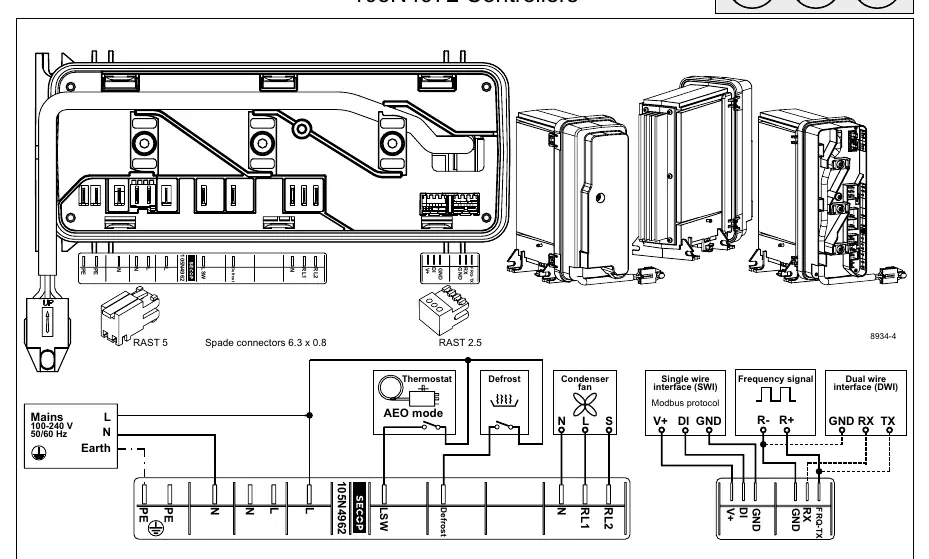
- Mains: 100-240V 50/60Hz connection (L, N, Earth).
- Interfaces: Supports Modbus protocol, Single wire interface (SWI), and Dual wire interface (DWI).
- Components: Connections for Thermostat, Defrost, and Condenser fan are clearly marked on the terminal block.
Installation and service
Proper installation is critical for the longevity of the compressor controller:
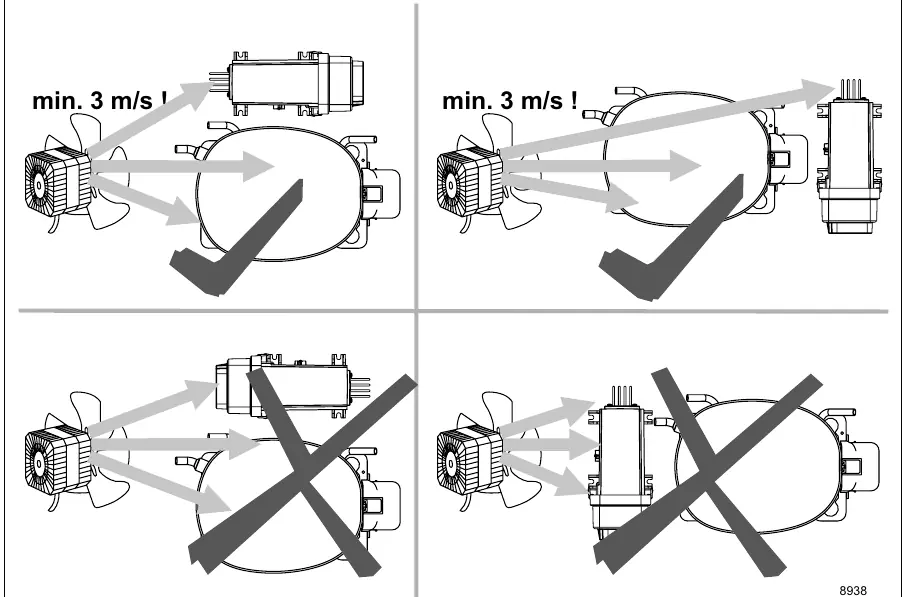
- Airflow: A minimum airflow of 3 m/s is required for proper operation.
- Safety: Keep electrical equipment clear from oil, chemicals, and water.
- Brazing: When brazing on suction connectors (direct intake), do not exceed 150°C (302°F) at the socket. Use phosphor (LP7) or silver brazing solder.
Technical specifications
The following operating parameters apply to the NLV compressor controllers:
- Supply voltage: 100-240 V (± 10 %)
- Frequency: 50/60 Hz
- Input power (max): 1000 W
- Operating conditions: +5°C to 43°C, humidity < 90% RH (non-condensing)
- Storage conditions: -25°C to 70°C, humidity < 90% RH (non-condensing)
Practical help
Common problems
Insufficient airflow
Ensure a minimum airflow of 3 m/s is maintained to prevent overheating.
Brazing damage
Do not exceed 150°C (302°F) at the socket when brazing suction connectors.
Before use
- Verify supply voltage is within 100-240V AC range.
- Ensure the installation environment provides at least 3 m/s airflow.
- Check that all electrical connections match the wiring diagram.
- Ensure the area is free from oil, chemicals, and water.
- Confirm the controller model (105N4962, 105N4966, or 105N4972) is correct for the application.
Specs in practice
- Supply voltage
- 100-240V (± 10%) range allows for global power compatibility.
- Max Input Power
- 1000W is the maximum power rating for the connected compressor system.
Images and diagrams
- The wiring diagram illustrates the terminal layout for mains power, thermostat, defrost, and fan connections.
- Specific sections detail the pinouts for Modbus, Single wire interface (SWI), and Dual wire interface (DWI).
Model compatibility
- Compatible with R290 refrigerant systems.
- Designed for use with Secop NLV series compressors.

Manual page author
David Miller
Documentation analyst
Organizes user manual content into clear summaries, with attention to model details, product context, and everyday usability.