HVAC / Compressor Controllers
Secop 105N467x Series Controller Instructions
Quick guide for the Secop 105N467x series controller. Includes detailed wiring diagrams, pinout configurations, electrical specifications, and essential safety requirements for R290 refrigerant systems.
Table of contents
Manual images
Click an image to enlargeImportant information
This document provides essential wiring, installation, and safety information for the Secop 105N467x series controller used with SLV compressors. Ensure all electrical connections are made according to the provided diagrams and that the system meets the required airflow and environmental conditions before operation.
Wiring and connections
The controller features specific terminals for mains power, relays, sensors, and communication. Refer to the wiring diagram for precise pin assignments:
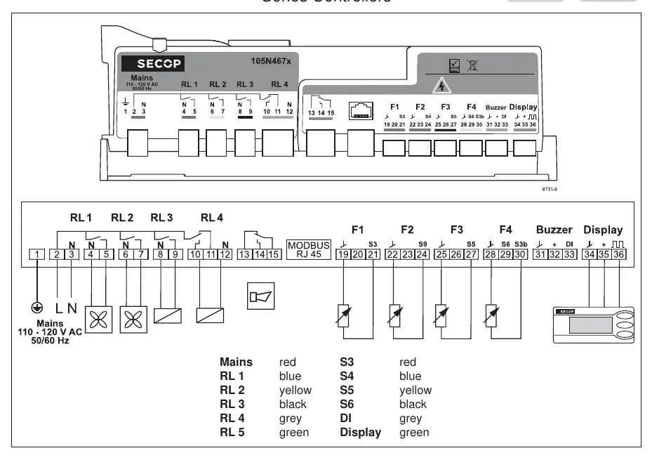
- Mains: 110-120V AC 50/60Hz.
- Relays (RL1-RL4): Control outputs for various system components.
- Sensors (S3-S6): Inputs for monitoring system parameters.
- Communication: Modbus RJ45 and Display connections.
Color Coding:
- Mains: red
- RL 1: blue
- RL 2: yellow
- RL 3: black
- RL 4: grey
- RL 5: green
- S3: red
- S4: blue
- S5: yellow
- S6: black
- DI: grey
- Display: green
Operating conditions and specifications
To ensure proper performance and longevity of the controller and compressor, adhere to the following specifications:
- Supply voltage: 115 V (+15 % / - 20 %)
- Frequency: 50/60 Hz
- Input power rating: 1000 W at 115 V (+15 % / - 20 %)
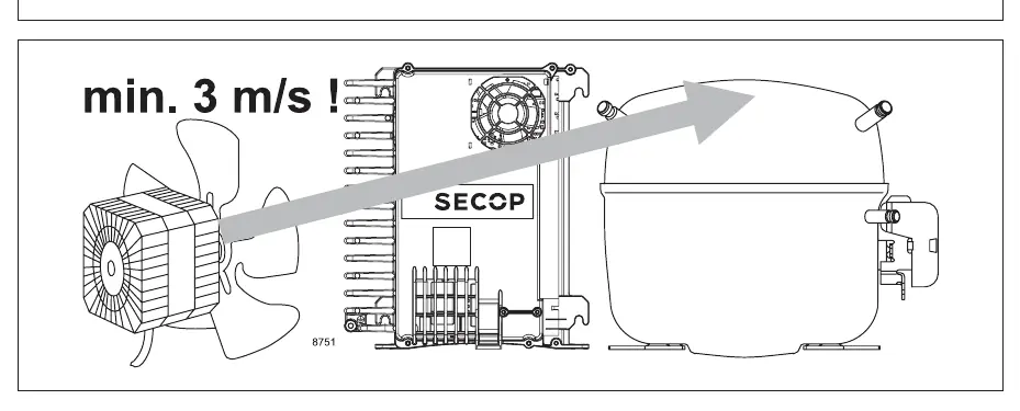
- Airflow requirement: Minimum 3 m/s
- Operating temperature: -14 °F to 109 °F (-25 °C to 43 °C)
- Storage temperature: -4 °F to 158 °F (-20 °C to 70 °C)
- Humidity: < 90 % rH non-condensing
Service and safety
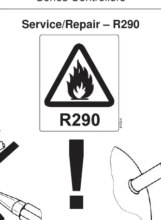
R290 Refrigerant: When performing service or repairs on systems using R290, exercise extreme caution. R290 is a flammable refrigerant. Ensure proper handling procedures are followed to prevent leaks or ignition hazards. Always use appropriate tools and follow safety protocols for flammable refrigerants.
Practical help
Common problems
Insufficient cooling or system failure
Check that the airflow is at least 3 m/s. Ensure the controller is not overheating.
Electrical connection errors
Verify all wiring against the color-coded pinout diagram provided in the manual.
Before use
- Verify supply voltage is 115V (+15%/-20%).
- Ensure the installation environment provides at least 3 m/s airflow.
- Check that all sensor and relay connections match the color-coded diagram.
- Confirm operating temperature is within -14 °F to 109 °F.
- Ensure humidity is below 90% and non-condensing.
Specs in practice
- Supply voltage
- 115 V (+15% / -20%) - The acceptable range for input power.
- Input power rating
- 1000 W - Maximum power consumption at 115V.
Images and diagrams
- The wiring diagram illustrates the connection points for Mains, Relays (RL1-RL4), Sensors (S3-S6), and the Display/Modbus interface.
- The service diagram highlights the specific safety requirements when working with R290 refrigerant systems.
Model compatibility
- Designed for SLV Compressors.
- Compatible with 110-120V 50/60Hz power supplies.

Manual page author
David Miller
Documentation analyst
Organizes user manual content into clear summaries, with attention to model details, product context, and everyday usability.