HVAC / Compressor Controllers
Installation and Wiring Guide for Secop NLV Compressor Controllers
Comprehensive installation and wiring guide for Secop NLV compressor controllers, including 105N4960, 105N4962, 105N491x, and 105N486x series. Covers electrical connections, airflow requirements, and service safety.
Table of contents
Manual images
Click an image to enlargeImportant Information
This document provides installation and wiring instructions for Secop NLV compressor controllers. Ensure that all electrical equipment is kept clear from oil, chemicals, and water. Proper airflow is critical for the operation of these units.
Wiring and Connections
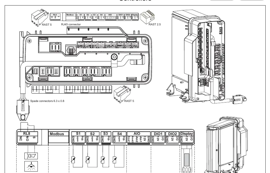
The controllers support various connection types including RAST 5, RAST 2.5, and spade connectors (6.3 x 0.8). Depending on the specific controller model, the following interfaces may be available:
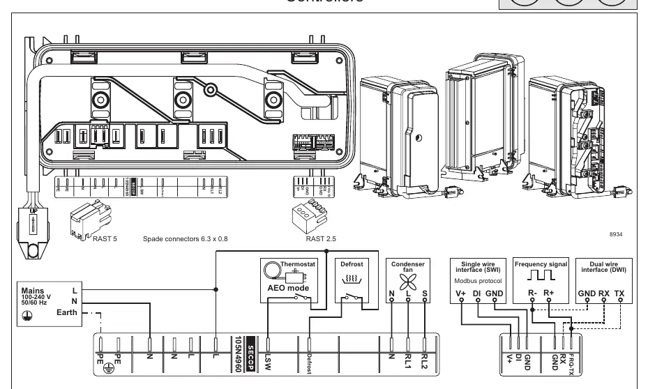
- Single wire interface (SWI)
- Modbus protocol
- Dual wire interface (DWI)
- Frequency signal
Refer to the wiring diagram specific to your controller model (105N4960, 105N4962, 105N491x, or 105N486x) to identify the correct terminals for Mains, Thermostat, Defrost, Condenser fan, and communication interfaces.
Installation and Airflow
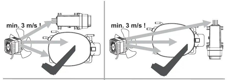
Proper cooling is essential for the compressor. A minimum airflow of 3 m/s must be maintained across the compressor unit. Ensure that the fan is positioned to direct air effectively over the compressor as shown in the installation diagrams.
Service and Maintenance
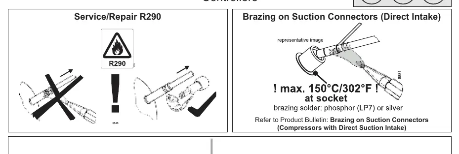
When performing service or repairs on systems using R290 refrigerant, follow all safety protocols. When brazing on suction connectors (direct intake), ensure the temperature at the socket does not exceed 150°C (302°F). Use phosphor (LP7) or silver brazing solder.
Technical Specifications
The following specifications apply to the NLV compressor controllers:
- Supply voltage: 100-240 V (± 10%) or 220-240 V (± 10%) depending on the model.
- Frequency: 50/60 Hz.
- Input power, max: 1000 W.
- Operating conditions: +5°C to 43°C, humidity < 90% rH (non-condensing).
- Storage conditions: -25°C to 70°C, humidity < 90% rH (non-condensing).
Practical help
Common problems
Compressor overheating
Ensure that the airflow across the compressor is at least 3 m/s.
Wiring connection errors
Verify the connection type (RAST 5, RAST 2.5, or Spade) against the specific wiring diagram for your controller model.
Before use
- Verify that the supply voltage matches the controller specifications (100-240V or 220-240V).
- Ensure the installation environment provides at least 3 m/s of airflow.
- Check that the electrical equipment is free from oil, chemicals, and water.
- Confirm the wiring interface (Modbus, Single wire, Dual wire, or Frequency signal) matches your system requirements.
Specs in practice
- Supply voltage
- 100-240 V or 220-240 V (± 10%) depending on the specific controller series.
- Input power, max
- Maximum power consumption is 1000 W.
Images and diagrams
- Wiring diagrams illustrate the connection points for Mains, Thermostat, Defrost, Condenser fan, and communication interfaces.
- Airflow diagrams indicate the required direction of air movement for cooling.
Model compatibility
- Compatible with R290 refrigerant systems.
- Wiring diagrams vary by controller series (105N4960, 105N4962, 105N491x, 105N486x).

Manual page author
Michael Turner
Technical manual editor
Reviews PDF manuals for structure, safety notes, and practical product details so readers can find the right information quickly.