HVAC / Compressor Controllers
Operating Instructions for Secop 105N4120 Core Functions Controller
Quick guide for the Secop 105N4120 Core Functions Controller. Includes installation, wiring diagrams, speed control modes (AEO, Frequency, DWI), and technical specifications for NLV-CN compressors.
Table of contents
Manual images
Click an image to enlargeQuick guide from the manual
The Secop 105N4120 is a Core Functions Controller designed for NLV-CN series compressors. This document provides essential installation, wiring, and operation guidelines. Key safety requirements include ensuring installation is performed by trained personnel, maintaining a 3 m/s airflow at both the compressor and electronic units, and ensuring all protective earth lines are connected to a single star point.
Installation
Proper installation is critical for the longevity and performance of the controller and compressor.
- Airflow: Ensure a minimum airflow of 3 m/s at both the compressor and electronic units. Airflow for the electronics must be directed specifically to the heat sink.
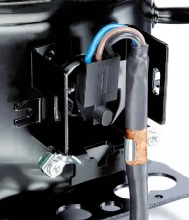
- Earthing: Both the compressor and controller must be connected to Protective Earth (PE) to prevent electrical hazards. All PE lines in the application must be collected to one star point to prevent loop currents.
- Cable Management: The copper shield of the controller cable must be fastened properly in the clip at the compressor for optimum EMC performance. Signal lines must be separated from power lines, and signal cable length should not exceed 3 meters.
Wiring
The controller features six connection points:
- Protective Earth (Mandatory)
- Neutral (Mandatory)
- Line (Mandatory)
- Thermostat/AEO (For AEO only)
- Defrost (For AEO and defrost only)
- Frequency/DWI (For frequency or DWI only)
Warning: Do not remove the cover of the controller when the unit is powered on. Disconnect from power and wait 30 seconds before accessing terminals.
Speed Control
The controller supports three input methods for speed control, with automatic input detection:
- Frequency signal: Speed changes linearly between 66 Hz and 150 Hz. Frequencies between 10-50 Hz cause the compressor to stop.
- Thermostatic operation with AEO (Adaptive Energy Optimization): Automatically calculates speed based on runtime. Ideal for stable conditions like freezers.
- DWI (Dual Wire Interface): A bidirectional communication protocol for speed control and monitoring.
If multiple signals are connected, the input with the highest priority is used. DWI has the lowest priority unless an active start command is sent.
Defrost Control
To improve defrost performance when using AEO, connect the relay output of the temperature controller to the DEF input. This enables two-speed defrosting, which helps avoid liquid refrigerant inside the compressor. After defrosting, the controller runs the first cycle at high speed to remove heat efficiently.
Technical Data
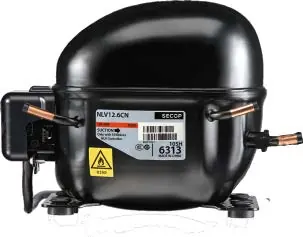
The 105N4120 controller operates on 220–240V AC (50/60 Hz). It features IP31 protection and is compatible with NLV8.0CN, NLV10CN, and NLV12.6CN compressors. The speed range is 2000–4500 rpm.
Practical help
Common problems
Compressor stops unexpectedly
Check if the frequency signal is between 10-50 Hz, which triggers a stop.
Defrosting not working properly
Ensure the relay output of the temperature controller is connected to the DEF input of the controller.
EMI or communication issues
Ensure signal lines are separated from power lines and that the signal cable length does not exceed 3 meters.
Before use
- Ensure installation is performed by trained personnel.
- Verify power supply is 220-240V AC.
- Check that the controller is connected to Protective Earth (PE).
- Ensure airflow of at least 3 m/s at both compressor and electronic units.
- Confirm signal cable length does not exceed 3 meters.
Specs in practice
- Nominal voltage
- 220–240V AC
- Max power input
- 1000 W
Images and diagrams
- Wiring diagrams show connections for Thermostatic Operation and Frequency/DWI Communication.
- Airflow diagrams illustrate the required 3 m/s airflow direction towards the heat sink.
Model compatibility
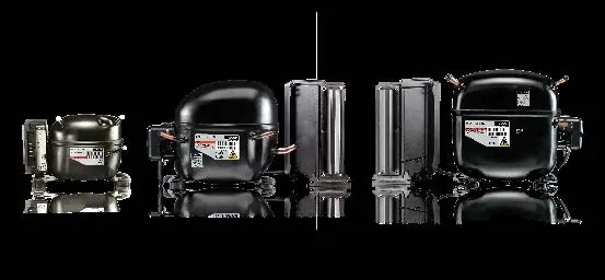
- Compatible with NLV8.0CN, NLV10CN, and NLV12.6CN compressors.
- Designed for LBP/MBP applications.

Manual page author
Emily Carter
User documentation editor
Prepares concise manual descriptions and highlights the most useful setup, operation, and maintenance information for readers.