Smart Home / Smart Switches
User Manual for Shelly Qubino Wave 1PM Smart Switch
Comprehensive user guide for the Shelly Qubino Wave 1PM smart switch. Includes installation instructions, wiring diagrams for AC/DC, Z-Wave inclusion/exclusion, LED status indicators, and technical specifications.
Quick answers from the manual
Quick answer
- The Shelly Qubino Wave 1PM is a Z-Wave smart switch for controlling electrical circuits (up to 3.5kW AC) with power measurement. It supports both AC (110-240V) and DC (24-30V) power supplies. p. 1
Key actions
- Inclusion (SmartStart) p. 1
- Factory Reset p. 1, 2
First start
- Connect to power, ensure LED blinks in Mode 1, then use gateway to include. p. 1
Problems and fixes
Over-current detected
Check connected load; LED blinks red Mode 4 (1x).
p. 1
Overheat detected
Check load/environment; LED blinks red Mode 4 (2x).
p. 1Maintenance and reset
- Factory reset via S button p. 1, 2
Technical specifications
| Parameter | Value | Meaning | Pages |
|---|---|---|---|
| Max AC Current | 16 A | Maximum switching current AC | p. 1 |
| Max DC Current | 10 A | Maximum switching current DC | p. 1 |
Where to find it in the PDF
- Installation and Wiring p. 1
- Z-Wave Inclusion/Exclusion p. 1, 2
Table of contents
Quick guide from the manual
The Shelly Qubino Wave 1PM is a Z-Wave smart switch designed to control electrical circuits (up to 3.5 kW AC) and measure power consumption. It supports both 110-240V AC and 24-30V DC power supplies. Installation must be performed by a qualified electrician. Always ensure power is disconnected before working on the device.
About the device
The Wave 1PM allows remote control of electrical devices like bulbs, ceiling fans, or IR heaters via a Z-Wave gateway. It acts as a Z-Wave repeater to increase network reliability. The device is compatible with standard push-buttons and switches.
Installation
Safety Warning: Danger of electrocution. Ensure the breaker is off and there is no voltage on the terminals before starting. Use solid single-core wires with PVC T105°C insulation.
Wiring
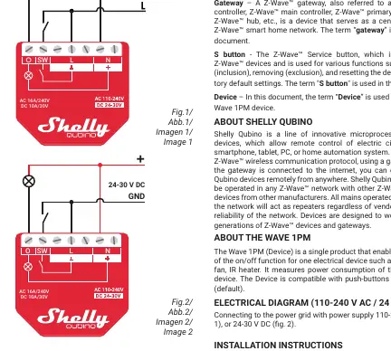
- AC Power Supply (110-240V AC): Connect the load to the O terminal and the Neutral wire to the N terminal. Connect the Live wire to an L terminal. Connect the switch/push-button to the SW terminal and an unused L terminal.
- DC Power Supply (24-30V DC): Connect the load to the O terminal and the + wire. Connect the GND wire to a terminal. Connect the + wire to a + terminal. Connect the switch/push-button to the SW terminal and an unused terminal.
Z-Wave Inclusion/Exclusion
SmartStart Inclusion: Scan the Z-Wave QR code on the device label with your gateway application. The device will be added automatically within 10 minutes of being powered on.
Manual Inclusion/Exclusion:
- Connect the device to power.
- Ensure the blue LED is blinking in Mode 1 (indicating it is not added to a network).
- Enable add/remove mode on your gateway.
- Toggle the switch/push-button connected to the SW terminal 3 times within 3 seconds, OR press and hold the S button until the LED turns solid blue, then release and press/hold (>2s) until the LED blinks in Mode 3.
LED Indicators
- Mode 1: 0.5s On / 2s Off (Ready for inclusion)
- Mode 2: 0.5s On / 0.5s Off (Inclusion/Exclusion process)
- Mode 3: 0.1s On / 0.1s Off (Learn mode)
- Mode 4: Blinking red (Alarm: Over-current, Overheat, or Power supply fault)
- Mode 5: 0.2s Blue / 0.2s Red (Checking power supply)
Factory Reset
Using Switch/Push-button: Toggle the switch connected to the SW terminal 5 times within 3 seconds (only possible within the first minute after connecting to power).
Using S Button: Press and hold the S button until the LED turns solid blue. Press multiple times until the LED turns solid red. Press and hold (>2s) until the red LED blinks in Mode 3.
Technical Specifications
- Power Supply: 110-240V AC / 24-30V DC
- Max Switching Current (AC): 16A
- Max Switching Current (DC): 10A
- Power Consumption:< 0.3W
- Z-Wave Repeater: Yes
- Operating Temperature: -20°C to 40°C
Practical help
Common problems
Device not recognized by gateway
Ensure your gateway supports Z-Wave Plus multi-level devices. You may need to change the device type manually in the gateway settings.
Over-current detected (LED blinks red Mode 4, 1x)
Check the connected load to ensure it does not exceed the maximum specified current (16A AC / 10A DC).
Overheat detected (LED blinks red Mode 4, 2x)
Ensure the device is installed in a suitable environment and the load is within limits.
Power supply fault (LED blinks red Mode 4, 3x)
Check the power supply frequency (230V AC) or voltage (24V DC) for stability.
Before use
- Ensure the main breaker is turned off.
- Verify zero voltage on terminals using a multimeter or phase tester.
- Use solid single-core wires with increased insulation heat resistance (PVC T105°C).
- Do not exceed the maximum load (16A AC / 10A DC).
- Do not shorten the antenna.
- Place the antenna away from metal objects to avoid signal interference.
Specs in practice
- Max Switching Current AC
- 16A - The maximum current the switch can handle for AC loads.
- Max Switching Current DC
- 10A - The maximum current the switch can handle for DC loads.
- Z-Wave Repeater
- The device acts as a signal repeater to extend the range of your Z-Wave network.
Images and diagrams
- Fig 1: Wiring diagram for 110-240V AC power supply.
- Fig 2: Wiring diagram for 24-30V DC power supply.
- Fig 3: Location of the S button for manual inclusion, exclusion, and factory reset.
Model compatibility
- Compatible with push-buttons and switches (default).
- Supports resistive, capacitive, and inductive loads.
- For inductive loads (motors, fans), use an RC snubber (0.1µF / 100Ω / 1/2W / 600V AC) in parallel.

Manual page author
Emily Carter
User documentation editor
Prepares concise manual descriptions and highlights the most useful setup, operation, and maintenance information for readers.