Lighting / LED Drivers
User Manual for Sunricher ZigBee 2-Gang In-wall Switch
Quick guide for the Sunricher ZigBee 2-Gang In-wall Switch. Includes installation wiring diagrams, pairing instructions, TouchLink setup, and troubleshooting.
Quick answers from the manual
Quick answer
- The Sunricher ZigBee 2-Gang In-wall Switch is a 2-channel ZigBee 3.0 receiver. It supports TouchLink, Find and Bind, and Green Power switches. It requires a neutral wire and is installed in a standard wall box. p. 1
Key actions
- Pairing with Hub p. 1
- Factory Reset p. 2
First start
- Ensure power is off, wire the device according to the diagram, then power on and initiate pairing mode. p. 1, 3
Problems and fixes
Device not responding
Check if the device is added to a network; the LED indicator stays solid on if added, off if not.
p. 1Maintenance and reset
- Press the Reset key 5 times or cycle power 5 times. p. 2
Technical specifications
| Parameter | Value | Meaning | Pages |
|---|---|---|---|
| Input Voltage | 100-240VAC | Operating voltage range | p. 1 |
| Max Load (Resistive) | 5.1A/CH | Maximum resistive load per channel | p. 1 |
Where to find it in the PDF
- Product Overview and Specs p. 1
- Pairing and Reset Procedures p. 2
- Wiring Diagrams p. 3, 4
Table of contents
Manual images
Click an image to enlargeQuick guide from the manual
The Sunricher ZigBee 2-Gang In-wall Switch is a ZigBee 3.0 device designed to control two separate lighting channels. Important: Always turn off the power supply before installation. Do not expose the device to moisture. The device supports resistive and capacitive loads, with a maximum load of 5.1A per channel for resistive loads and 1.7A per channel for capacitive loads.
Wiring and Installation
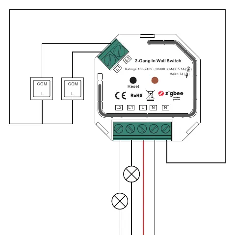
The device requires a neutral wire for installation. Ensure wiring is performed according to the provided diagrams.
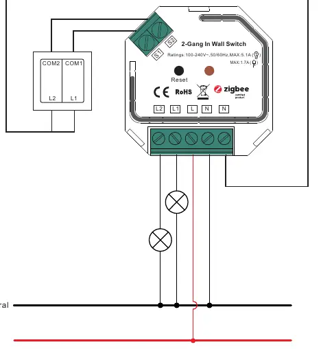
- L: Terminal for live lead.
- N: Terminal for neutral lead.
- S1: Terminal for switch key No. 1.
- S2: Terminal for switch key No. 2.
- L1: Output terminal No. 1 for light load.
- L2: Output terminal No. 2 for light load.
The device can be configured for Push Switches (factory default) or Toggle On/Off Switches.
ZigBee Network Pairing
To add the device to a ZigBee network:
- Remove the device from any previous network (perform a factory reset if necessary).
- Set your ZigBee controller or hub to pairing mode.
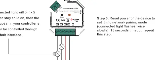
- Reset the power of the device (or press the Reset button) to enter pairing mode. The connected light will flash twice.
- The light will blink 5 times and stay solid when successfully paired.
TouchLink and Remote Control
The device supports TouchLink commissioning for direct pairing with remotes without a coordinator.
- Bring the remote or touch panel within 10cm of the switch.
- Set the remote to TouchLink commissioning mode.
- The device will indicate a successful link when the connected light flashes.
Factory Reset
If the device needs to be reset to factory settings:
- Using the Reset Key: Short press the "Reset" key 5 times continuously.
- Using Power: Reset the power of the device 5 times continuously if the key is inaccessible.
- The connected light will blink 3 times to indicate a successful reset.
Technical Specifications
- Input Voltage: 100-240VAC
- Output Channels: 2
- Max Load (Resistive): 5.1A per channel
- Max Load (Capacitive): 1.7A per channel
- Radio Frequency: 2.4GHz
- Waterproof Grade: IP20
Practical help
Common problems
Device fails to pair with ZigBee network
Ensure the device is removed from any previous network first. Perform a factory reset by pressing the Reset key 5 times.
TouchLink commissioning fails
Ensure the remote or touch panel is within 10cm of the switch during the process.
Relay turns off unexpectedly
The device has over-current protection. If the total load exceeds 8.1A, the relay will force off.
Before use
- Ensure power is turned off before installation.
- Verify that a neutral wire is available in the wall box.
- Check that the load type (resistive or capacitive) is within the specified limits.
- Ensure the ZigBee controller is ready for pairing.
Specs in practice
- Input Voltage
- 100-240VAC, compatible with standard mains power.
- Max Load (Resistive)
- 5.1A per channel; maximum current for resistive loads like incandescent bulbs.
- Max Load (Capacitive)
- 1.7A per channel; maximum current for capacitive loads like LED drivers.
Images and diagrams
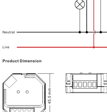
- L and N terminals are for AC power input.
- S1 and S2 terminals connect to external wall switches.
- L1 and L2 terminals connect to the lighting loads.
Model compatibility
- Compatible with universal ZigBee gateway products.
- Supports ZigBee Green Power switches (max 20).
- Supports firmware updates via OTA.

Manual page author
Michael Turner
Technical manual editor
Reviews PDF manuals for structure, safety notes, and practical product details so readers can find the right information quickly.