Lighting / Controllers & Dimmers
User Manual for Shelly Plus 0-10V Dimmer
Quick guide for the Shelly Plus 0-10V Dimmer. Includes installation instructions, wiring diagrams, safety warnings, and technical specifications for this smart 0-10V dimming controller.
Table of contents
Quick guide from the manual
The Shelly Plus 0-10V Dimmer is a smart controller designed to manage 0-10V dimmable LED drivers. It is not intended to directly control LED lights. Installation must be performed by a qualified electrician. The device requires a 110-240 VAC power supply and must be protected by a circuit breaker (max 2A, B or C characteristic). Always ensure power is disconnected before performing any wiring.
Product Description
Shelly Plus 0-10V Dimmer is a microprocessor-managed device that allows remote control of electric circuits via mobile phone, tablet, PC, or home automation systems. It supports local Wi-Fi operation or cloud-based control via the Shelly Cloud service. The device features an embedded web interface for monitoring and configuration.
Installation Instructions
Safety Warning: Danger of electrocution. Mounting and installation must be performed by a qualified electrician. Ensure no voltage is present at the terminals before starting.
Wiring Steps:
- Connect the Live wire (110-240 VAC) to the L terminal.
- Connect the Neutral wire to the N terminal.
- Connect the positive output (+) of the device to the 0-10V positive input of the LED driver.
- Connect the negative output (-) of the device to the 0-10V negative input of the LED driver.
- Connect switches or buttons to the S1 and S2 terminals and the Live wire.
Important: Do not use buttons or switches with built-in LED or glow-lamps. The device can work in single or dual button modes or single switch mode. In single input mode, S2 is detached.
Initial Inclusion
The device can be used with the Shelly Smart Control mobile application and cloud service. Instructions for connecting to the cloud are available in the mobile application guide. The device can also be used standalone or with other home automation platforms. The embedded web interface is accessible at http://192.168.33.1 when connected to the device's access point.
Specifications
- Power supply: 110 - 240 VAC, 50/60Hz
- Electrical consumption: < 1.2 W
- Max control voltage: 10 V
- Max control current: 35 mA
- PWM frequency: 500 Hz
- Wi-Fi protocol: 802.11 b/g/n
- Bluetooth protocol: 4.2
- Dimensions: 37x42x16 mm
Safety and Compliance
Do not open the device. It contains no user-serviceable parts. Unauthorized modification is prohibited. Ensure the device is protected by a cable protection switch in accordance with EN60898-1 (max 2A, 6kA interrupting rating, energy limiting class 3). Keep the device away from water and children.
Practical help
Common problems
Device not responding or not connecting to Wi-Fi
Ensure the device is powered correctly and check the Wi-Fi router connection. Access the embedded web interface at 192.168.33.1 to verify settings.
LED lights flickering or not dimming correctly
Verify that the LED driver is compatible with 0-10V sinking control. Ensure wiring to the + and - terminals is correct and secure.
Switch not working
Ensure you are not using switches with built-in LED or glow-lamps, as these are not supported.
Before use
- Ensure power is turned off at the circuit breaker.
- Verify voltage is absent at terminals using a multimeter.
- Ensure the LED driver supports 0-10V sinking control.
- Use solid single-core wires or stranded wires with ferrules.
- Check that the circuit breaker is rated for max 2A (B or C characteristic).
Specs in practice
- 0-10V Control Type
- Sinking (the device pulls current from the 0-10V signal line).
- Max Control Current
- 35 mA (do not exceed this load on the control output).
- Power Supply
- 110-240 VAC, 50/60Hz.
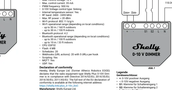
Images and diagrams
- L terminal: Connect to Live wire (110-240 VAC).
- N terminal: Connect to Neutral wire.
- S1/S2 terminals: Connect to switches or buttons.
- +/- terminals: Connect to the 0-10V input of the LED driver.
Model compatibility
- Not intended to directly control LED lights; must be used with a 0-10V LED driver.
- Do not use buttons or switches with built-in LED or glow-lamp.

Manual page author
Michael Turner
Technical manual editor
Reviews PDF manuals for structure, safety notes, and practical product details so readers can find the right information quickly.