Tools / Generators
Equipment Manual for Siemens SIMATIC ET 200SP CPU 1512SP-1 PN
Comprehensive equipment manual for the Siemens SIMATIC ET 200SP CPU 1512SP-1 PN. This guide covers hardware installation, wiring, LED status diagnostics, and technical specifications for the 6ES7512-1DM03-0AB0 controller.
Table of contents
Manual images
Click an image to enlargeQuick guide from the manual
This equipment manual provides essential information for the Siemens SIMATIC ET 200SP CPU 1512SP-1 PN (Article number: 6ES7512-1DM03-0AB0). It is intended for qualified personnel responsible for installation, commissioning, and maintenance. Always refer to the full documentation for detailed system-spanning functions.
Product Overview
The CPU 1512SP-1 PN is a high-performance controller for the ET 200SP distributed I/O system. Key features include:
- Integrated PROFINET interface with 3-port switch.
- Support for PROFINET IO, IRT, and isochronous mode.
- Firmware version V3.1 with enhanced security and diagnostic functions.
- Support for S7-1500 Motion Control technology objects.
- Integrated web server for remote diagnostics and monitoring.
Wiring and Connections
Proper wiring is critical for safe operation:
- Supply Voltage (X80): The 24V DC supply is connected via a 4-pin plug. Pins 1L+ and 2L+ are for 24V DC, while 1M and 2M are for ground.
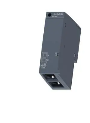
- PROFINET Interface (X1): Port 3 is integrated into the CPU housing. Ports 1 and 2 are available via an optional BusAdapter.
- MAC Addresses: The device has four MAC addresses (one for the interface, three for the ports) used for protocols like LLDP.
Status and Error Displays
The CPU features several LEDs to indicate operational status:
- POWER (PWR): Indicates supply voltage status.
- RUN/STOP: Displays the current operating mode (Green = RUN, Yellow = STOP).
- ERROR: Flashes red when an error occurs.
- MAINT: Indicates maintenance demand (Yellow).
- LINK LEDs: Indicate Ethernet connection status for PROFINET ports.
Technical Specifications
- Supply Voltage: 24V DC (permissible range 19.2V to 28.8V).
- Work Memory: 400 kbyte for program, 2 Mbyte for data.
- Operating Temperature: -30°C to 60°C (horizontal installation).
- Dimensions: 100mm (W) x 117mm (H) x 75mm (D).
- Weight: Approx. 265g.
Safety and Cybersecurity
Siemens strongly recommends implementing a holistic industrial cybersecurity concept. Ensure the CPU is protected against unauthorized access by locking the front flap and using password protection. Always apply the latest product updates to mitigate cyber threats.
Manufacturer information
Siemens AG
Practical help
Common problems
Missing or insufficient supply voltage
Check the 24V DC supply at the X80 connector. Ensure the plug is correctly seated.
ERROR LED flashing red
An error has occurred. Check the CPU diagnostic buffer for specific error details.
No Ethernet connection
Verify the PROFINET cable connection and check the LINK LED status on the port.
Firmware update failed
Ensure the SIMATIC Memory Card is correctly inserted and the update file is valid.
Before use
- Verify the article number 6ES7512-1DM03-0AB0.
- Ensure a 24V DC power supply is available.
- Check if a BusAdapter is required for your network topology.
- Confirm the firmware version is compatible with your TIA Portal project.
- Ensure the SIMATIC Memory Card is available if required for the program.
Specs in practice
- Supply voltage
- 24V DC nominal (19.2V - 28.8V range).
- Operating temperature
- -30°C to 60°C for horizontal installation; -30°C to 50°C for vertical.
Images and diagrams
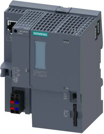
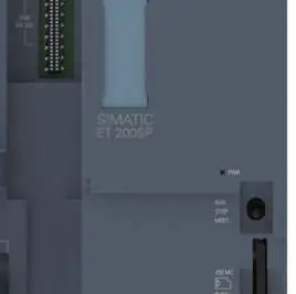
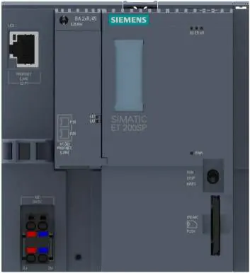
- The front view shows the mode switch, memory card slot, and LED indicators.
- The wiring diagram for X80 details the 24V DC supply pinout.
- The dimension drawing provides the necessary clearance for cabinet installation.
Model compatibility
- Requires TIA Portal for configuration and programming.
- Supports PROFINET IO and PROFIBUS DP (via optional CM DP module).
- Compatible with various BusAdapters (e.g., BA 2xRJ45, BA 2xM12).

Manual page author
David Miller
Documentation analyst
Organizes user manual content into clear summaries, with attention to model details, product context, and everyday usability.