Electronics / Remote Controls
User Manual for Skytech 1001-A Remote Control System
Quick guide for the Skytech 1001-A remote control system. Learn how to install, wire, pair security codes, and troubleshoot your fireplace remote.
Table of contents
Quick Guide
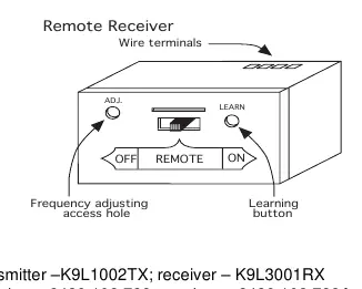
The Skytech 1001-A is a remote control system designed for gas heating appliances. It consists of a transmitter and a receiver. The receiver features a 3-position slide switch: ON (manual override), REMOTE (remote operation), and OFF (safety lock-out). For initial setup, ensure fresh alkaline batteries are installed in both units and the receiver is set to the REMOTE position to pair the security code.
System Overview
The transmitter operates on a 12V battery and sends signals to the receiver. The receiver operates on 4 AA batteries and connects to your gas valve or electronic module. The system uses one of 65,536 security codes to prevent interference.
Installation
The receiver can be wall-mounted in a plastic switch box or placed on the fireplace hearth. Protection from extreme heat is critical; ensure the ambient temperature inside the receiver case does not exceed 130°F. If wall-mounting, use the provided cover plate and screws. Ensure the receiver switch is in the OFF position during installation.
Wiring Instructions
Wiring must be performed by a qualified technician. Use 18-gauge solid or stranded wire (max 20 ft length).
Millivolt Valves
Connect the two wires from the TH (thermostat) terminals on the millivolt gas valve to the two wire terminals on the remote receiver. Polarity does not matter.
Electronic Spark Ignitions
Connect the system in series to a 24VAC transformer. Connect the hot wire from the transformer to one receiver terminal, and connect the other receiver terminal to the TH (thermostat) terminal on the electronic module.
System Check
After installation, verify operation:
- Millivolt: Slide receiver to ON; the main flame should ignite. Slide to OFF; the flame should extinguish. Slide to REMOTE and use the transmitter to turn the system ON.
- Electronic Ignition: Slide receiver to ON; the spark electrode should ignite the pilot, followed by the main flame. Slide to OFF; both flames should extinguish. Slide to REMOTE and use the transmitter to turn the system ON.
Matching Security Codes
If the system does not respond, you may need to program the receiver to learn the transmitter's code:
- Ensure the receiver slide switch is in the REMOTE position.
- Press the LEARN button on the top of the receiver.
- Press the MODE button on the transmitter.
- A beeping pattern at the receiver confirms the code has been programmed.
If unsuccessful, wait 1-2 minutes for the microprocessor to reset and try again.
Troubleshooting and Adjustment
If the remote range decreases or the system fails to operate, check the following:
- Ensure batteries are fresh and correctly oriented.
- Verify the receiver is within 20-25 feet of the transmitter.
- If the receiver is in a metal enclosure, the range may be reduced.
- Adjustment: If range is poor, use a small slotted screwdriver to turn the adjustment screw on the receiver counter-clockwise by about 5 degrees (max 1/8 turn). If this does not help, return to the original position and try turning clockwise.
Specifications
- Transmitter Battery: 12V (A23)
- Receiver Battery: 6V (4x AA Alkaline)
- Operating Frequency: 303.875 MHz
- Max Wire Length: 20 feet
Practical help
Common problems
Remote range has decreased or system does not respond
Check battery levels in both transmitter and receiver. Ensure receiver is within 20-25 feet. Adjust the frequency screw on the receiver.
System will not 'LEARN' the transmitter code
Ensure the receiver slide switch is in the REMOTE position. The code will not learn if the switch is in ON or OFF.
Receiver does not operate properly
Check for reversed batteries in the receiver. Ensure the receiver is not exposed to temperatures exceeding 130°F.
Before use
- Install fresh alkaline batteries in the transmitter (12V) and receiver (4x AA).
- Ensure the receiver slide switch is in the OFF position during installation.
- Verify that the receiver is mounted away from extreme heat (max 130°F).
- Confirm wiring connections to the gas valve or electronic module are secure.
- Ensure the receiver is in the REMOTE position for normal operation.
Specs in practice
- Operating Frequency
- 303.875 MHz; the radio frequency used for communication.
- Max Wire Length
- 20 feet; exceeding this may cause signal delivery issues due to voltage drop.
- Receiver Battery Voltage
- 6V total (4x 1.5V AA); electronics perform best when output is >5.3V.
Images and diagrams
- Receiver Slide Switch: ON (manual override), REMOTE (remote control), OFF (safety lock-out).
- Frequency Adjusting Screw: Used to fine-tune the receiver's signal reception range.
Model compatibility
- Compatible with millivolt gas valves and electronic spark ignition systems.
- Not for use with 110-120VAC power directly on the gas valve or electronic module.

Manual page author
David Miller
Documentation analyst
Organizes user manual content into clear summaries, with attention to model details, product context, and everyday usability.