Electronics / Remote Controls
Installation and Operation Manual for Skytech 001D-A Remote Control System
Comprehensive installation and operation guide for the Skytech 001D-A remote control system. Includes step-by-step instructions for battery installation, wall mounting, wiring for millivolt and electronic spark systems, and troubleshooting.
Table of contents
Manual images
Click an image to enlargeQuick Guide
The Skytech 001D-A is a remote control system designed for gas heating appliances. Before installation, ensure the receiver slide switch is in the OFF position. The system operates on a 20-25 foot range. Always use alkaline batteries for the receiver and ensure the receiver is not installed in a tightly enclosed metal surrounding, as this will reduce operating distance.
Battery Installation
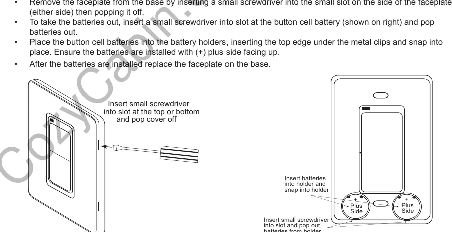
Transmitter: Remove the faceplate by inserting a small screwdriver into the side slot. Insert two 3-volt button cell batteries with the (+) side facing up. Snap the faceplate back on.
Receiver: Install four AA alkaline batteries. Ensure the (+) and (-) ends are facing the correct direction. It is recommended to replace batteries annually or when the operating range decreases.
Mounting the Transmitter
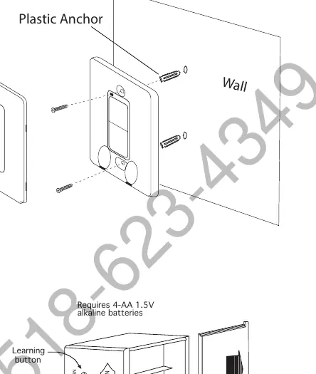
The transmitter can be mounted on a wall or an existing non-metal electrical box. Remove the faceplate, mark the two mounting holes on the wall, use the supplied dry wall anchors and screws to mount the base plate, and snap the faceplate back on.
Mounting the Receiver
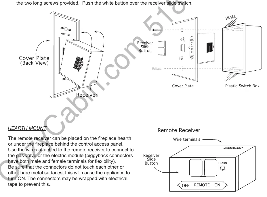
The receiver can be wall-mounted in a standard plastic switch box or placed on the fireplace hearth. If wall-mounting, use 18 AWG wires (not included) no longer than 20 feet. Ensure the receiver is kept away from temperatures exceeding 130°F. When attaching the cover plate, ensure the LEARN hole aligns with the receiver.
Wiring Instructions
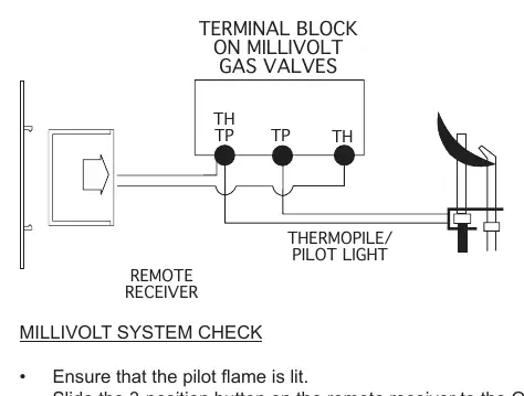
Millivolt Gas Valves: Connect one wire from the receiver to the TH terminal on the gas valve and the other wire to the TH/TP terminal.
Electronic Spark Ignition Systems: Connect the receiver in series to a 24VAC transformer. Connect the hot wire from the transformer to one receiver terminal, and connect the other receiver terminal to the TH (thermostat) terminal on the electronic module.
Learning Transmitter to Receiver
Each transmitter uses a unique security code. To pair: 1. Set the receiver slide switch to the REMOTE position. 2. Use a small screwdriver or paperclip to press the black LEARN button inside the hole on the receiver face. 3. The receiver will emit an audible beep. 4. Press the ON or OFF button on the transmitter for approximately 2 seconds. The receiver will emit several beeps to confirm the code is accepted.
Troubleshooting
If the system fails to operate: 1. Check that all batteries are fresh and correctly installed. 2. Ensure the receiver slide switch is in the REMOTE position. 3. Verify that the receiver is not in a metal enclosure. 4. Perform the Learning procedure again. 5. Ensure all wiring connections are secure and match the manufacturer's specifications for your gas appliance.
Practical help
Common problems
Indicator light on transmitter does not illuminate
Check that batteries are fully charged and installed with the correct polarity (+/-).
System does not respond to transmitter
Ensure the receiver slide switch is in the REMOTE position and perform the 'Learning' procedure to pair the transmitter.
Reduced operating range
Check battery levels, ensure the receiver is not inside a metal enclosure, and verify the distance is within 20-25 feet.
Before use
- Install (2) 3-volt button cell batteries in the transmitter.
- Install (4) AA alkaline batteries in the receiver.
- Ensure the receiver slide switch is in the OFF position during installation.
- Verify all wiring connections match the manufacturer's specifications for your gas valve or electronic module.
- Ensure the receiver is not placed in an area exceeding 130°F.
Specs in practice
- Operating Range
- 20 to 25 feet.
- Receiver Slide Switch
- ON (manual override), REMOTE (handheld control), OFF (disabled).
Images and diagrams
- Transmitter Battery Installation: Shows how to pop off the faceplate and insert button cell batteries.
- Receiver Wiring (Millivolt): Shows connection to TH and TH/TP terminals.
- Receiver Wiring (Electronic Spark): Shows connection to TR and TH terminals via a 24VAC transformer.
Model compatibility
- Designed for use with millivolt gas valves and electronic spark ignition systems.
- Not for use with 110-120VAC power directly on gas valves.
- Receiver should be kept away from temperatures exceeding 130°F.

Manual page author
Michael Turner
Technical manual editor
Reviews PDF manuals for structure, safety notes, and practical product details so readers can find the right information quickly.