Electronics / Remote Controls
User Manual for Skytech 1001D-A Remote Control System
Quick guide for the Skytech 1001D-A remote control system. Learn how to install batteries, mount the transmitter and receiver, wire the system to gas valves, and troubleshoot common issues.
Table of contents
Manual images
Click an image to enlargeQuick guide from the manual
The Skytech 1001D-A is a remote control system designed for gas heating appliances. This system allows for manual operation via a wall-mounted transmitter and a receiver unit. Important: This product is for use with attended hearth appliances only. Adults must be present when the system is operating. Do not leave the appliance burning unattended.
Safety and Warnings
- Do not connect any gas valve or electronic module directly to 110-120VAC power.
- Keep the receiver away from temperatures exceeding 130°F, as heat can damage components and shorten battery life.
- Improper installation can pose a fire hazard. Follow all wiring instructions carefully.
Transmitter Setup
The wall transmitter operates on two 3-volt button cell batteries (included).
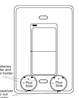
- Battery Installation: Remove the faceplate by inserting a small screwdriver into the side slot. Insert the batteries into the holders with the (+) side facing up. Snap the faceplate back onto the base.
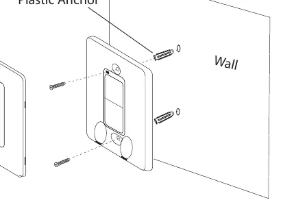
- Wall Mounting: Remove the faceplate, mark the mounting holes on the wall, and use the provided anchors and screws to mount the base plate. Snap the faceplate back on. It can also be mounted to an existing non-metal electrical box.
Receiver Setup
The receiver requires four AA alkaline batteries.
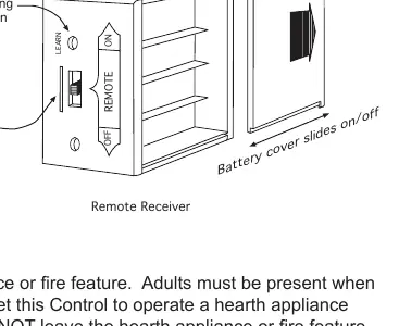
- Battery Installation: Slide the battery cover off the receiver and insert four AA batteries, ensuring correct polarity.
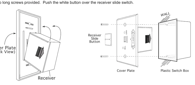
- Mounting: The receiver can be wall-mounted in a plastic switch box or placed on the fireplace hearth. If wall-mounting, ensure the receiver is protected from heat. Use 18 AWG wire (not included) for connections, no longer than 20 feet.
- Operation Modes: The receiver has a 3-position slide switch: ON (manually turns on appliance), REMOTE (allows transmitter use), and OFF (disables receiver).
Wiring Instructions
A qualified electrician should perform the installation.

- Millivolt Gas Valves: Connect one wire from the receiver to the TH terminal on the gas valve and the other wire to the TH/TP terminal.
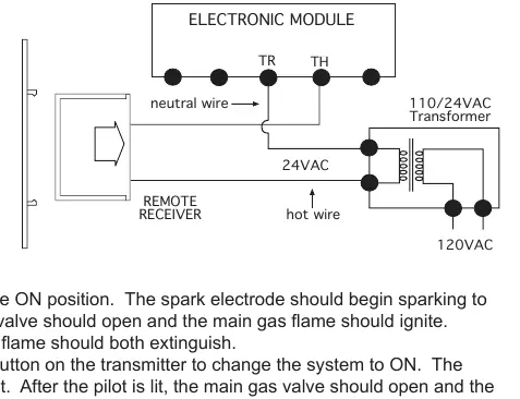
- Electronic Spark Ignition: Connect the receiver in series to a 24VAC transformer. Connect the hot wire from the transformer to one receiver terminal, and the other receiver terminal to the TH (thermostat) terminal on the electronic module.
Learning Transmitter to Receiver
Each transmitter uses a unique security code. To pair the transmitter:
- Ensure the receiver slide switch is in the REMOTE position.
- Locate the LEARN button on the front face of the receiver.
- Use a small screwdriver or paperclip to press and release the LEARN button. The receiver will emit an audible beep.
- Within a few seconds, press the ON or OFF button on the transmitter for approximately 2 seconds.
- The receiver will emit several beeps to confirm the code has been accepted.
Troubleshooting
If the system does not respond:
- Check that all batteries are fresh and correctly installed.
- Ensure the receiver slide switch is set to REMOTE.
- Verify the transmitter is within the 20-25 foot operating range.
- Perform the "Learning" procedure again to ensure the transmitter is paired.
- If the indicator light on the transmitter does not illuminate, check the transmitter batteries.
Practical help
Common problems
System does not respond to transmitter
Check battery orientation and charge. Ensure receiver switch is in REMOTE mode. Perform the 'Learning' procedure to re-pair the transmitter.
Indicator light on transmitter does not illuminate
The transmitter batteries are likely dead or installed incorrectly. Check the (+) and (-) orientation.
Appliance turns on unexpectedly
Ensure wire connectors are not touching each other or bare metal surfaces. Wrap connectors with electrical tape if necessary.
Before use
- Install two 3V button cell batteries in the transmitter.
- Install four AA alkaline batteries in the receiver.
- Ensure the receiver slide switch is in the OFF position during installation.
- Verify the gas valve type (millivolt or electronic spark) to use the correct wiring diagram.
- Ensure the receiver is not installed in a tightly enclosed metal surrounding.
Specs in practice
- Operating Range
- 20 to 25 feet. Distance may be reduced if the receiver is in a metal enclosure.
- Temperature Limit
- Keep receiver below 130°F to prevent damage and battery life reduction.
Images and diagrams
- Transmitter battery installation: Use a screwdriver to pop the faceplate, then insert batteries with the plus side up.
- Receiver wiring: Connect to TH and TH/TP terminals for millivolt valves; connect in series with a 24VAC transformer for electronic spark systems.
Model compatibility
- Designed for use with gas heating appliances.
- Not compatible with 110-120VAC power directly.
- Receiver should be mounted in a plastic (non-metal) box.

Manual page author
Emily Carter
User documentation editor
Prepares concise manual descriptions and highlights the most useful setup, operation, and maintenance information for readers.