Electronics / Remote Controls
Skytech 1001D Remote Control System User Manual
Comprehensive user manual for the Skytech 1001D remote control system. Includes installation instructions, wiring diagrams for millivolt and electronic spark ignition valves, system testing procedures, and troubleshooting tips.
Table of contents
Manual images
Click an image to enlargeQuick Guide
The Skytech 1001D is a radio frequency remote control system designed for gas heating appliances. It operates on one of 255 factory-programmed security codes with a range of approximately 20 feet. Warning: Do not connect the remote receiver directly to 110-120 VAC power, as this will destroy the unit. The receiver must be installed in a plastic switch box to avoid signal interference.
Components
The system includes:
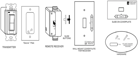
- Wall Transmitter
- Remote Receiver
- Wall-mount cover plate
- Hardware (screws and batteries)
Installation
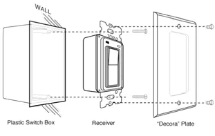
The remote receiver should be installed in a plastic switch box. Steel switch boxes can absorb the RF signal and reduce operating distance. Ensure the receiver is positioned where ambient temperatures do not exceed 130°F.
Wall Mount
Install four 1.5V AA alkaline batteries into the remote receiver. Position the receiver with the word 'TOP' facing up and secure it into the plastic switch box using the provided long screws. Attach the cover plate with the short screws and push the receiver slide button over the slide switch.
Hearth Mount
The receiver can be placed on the fireplace hearth or under the fireplace behind the control access panel. Ensure the battery compartment is on the bottom and the ambient temperature remains below 130°F.
Wiring Instructions
Warning: Improper wiring can damage the gas valve, electronic module, and remote receiver. Consult the gas appliance manufacturer's instructions for specific wiring schematics.
Wiring Millivolt Valves
Connect two 18-gauge wires from the remote receiver to the TH and TH/TP terminals on the millivolt gas valve. Polarity does not matter for these connections.
Wiring Electronic Spark Ignitions
Connect the neutral wire from the 24VAC transformer to the TR terminal on the electronic module. Connect the hot wire from the 24VAC transformer to one of the receiver wire terminals. Connect the remaining receiver wire terminal to the TH (thermostat) terminal on the electronic module.
System Check
Ensure the pilot flame is lit before testing. Set the 3-position slide switch on the receiver to the 'REMOTE' (center) position. Use the ON/OFF buttons on the transmitter to control the main gas flame. Upon initial use or after long periods of inactivity, hold the ON button for up to three seconds.
Troubleshooting and Maintenance
If the system fails to operate, check the following:
- Ensure batteries are fresh and correctly installed.
- Verify the receiver is not in a steel switch box.
- Ensure the receiver is within the 20-25 foot operating range.
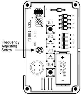
- If the range is poor, perform a frequency adjustment on the transmitter by turning the adjustment screw clockwise or counter-clockwise by no more than 1-2 degrees.
Practical help
Common problems
Remote control range is short or non-responsive
Check battery levels in both transmitter and receiver. Ensure the receiver is not installed in a steel switch box. Perform a frequency adjustment on the transmitter.
Receiver does not respond to transmitter
Ensure the 3-position slide switch on the receiver is set to the 'REMOTE' (center) position. Ensure the transmitter battery is installed correctly.
System does not turn on
Verify the pilot flame is lit. Ensure the receiver is not exposed to temperatures exceeding 130°F, which can shorten battery life and affect performance.
Before use
- Install 12V battery in the wall transmitter.
- Install four 1.5V AA alkaline batteries in the remote receiver.
- Ensure the receiver is installed in a plastic switch box.
- Verify the pilot flame is lit on the gas appliance.
- Set the receiver slide switch to the 'REMOTE' position.
Specs in practice
- Operating Frequency
- 303.875MHz
- Operating Range
- Approximately 20-25 feet
- Transmitter Battery
- 12V (A23)
- Receiver Batteries
- 4x 1.5V AA Alkaline
Images and diagrams
- The wiring diagrams illustrate connections for both millivolt gas valves and electronic spark ignition modules.
- The frequency adjustment screw is located inside the transmitter, to the left of the battery.
Model compatibility
- Do not connect the receiver directly to 110-120 VAC power.
- Use only plastic switch boxes for installation.
- Ambient temperature at the receiver location must not exceed 130°F.

Manual page author
David Miller
Documentation analyst
Organizes user manual content into clear summaries, with attention to model details, product context, and everyday usability.