Smart Home / Motor Controllers
Somfy SDN 0-10V Interface V2 Programming Guide
Comprehensive programming and installation guide for the Somfy SDN 0-10V Interface V2. Learn how to wire the device, configure DIP switches for SDN or animeo IP modes, and integrate with third-party lighting controls.
Table of contents
Manual images
Click an image to enlargeQuick guide from the manual
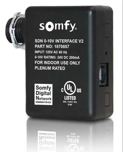
The Somfy SDN 0-10V Interface V2 is a device designed to convert standard 0-10V analog dimming signals into Somfy Digital Network (SDN) or animeo IP commands. It allows third-party lighting control systems to drive motors in 10% increments (0%-100%). This device is plenum-rated and intended for indoor use.
System Requirements
- Set pro by Somfy Configuration Software
- animeo IP Visual Configuration Software
- A fully commissioned standalone SDN or animeo IP project
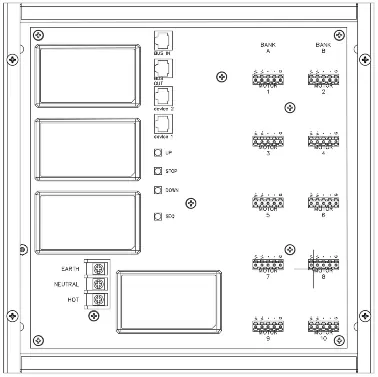
Connections and Indicators
The device features the following interface elements:
- 0-10V Input & Power: Flying leads for power and 0-10V wiring.
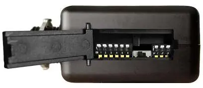
- DIP Switch Bank: Located behind an access door; used for mode selection and group address assignment.
- Push Button: Used for sequencing motor operation, animeo IP discovery, and power cycling.
- SDN Output: RJ45 port supplying SDN bus power and communication.
- Main Power LED: Solid green when powered.
- Bus Activity LED: Blinks green with SDN bus activity.
- Bus Power Switch: Enables +24V bus power to an SDN segment (Left=OFF, Right=ON).
Installation
This device must be installed by a qualified electrician. It utilizes a junction-box-mountable enclosure.
- Ensure the device is powered by AC line voltage.
- Connect the 0-10V input signal inside the junction box using the provided 2 wires.
- Connect the SDN Bus using a standard CAT-5e or higher cable to the RJ45 port.
- Ensure the Bus Power Switch is set correctly (OFF by default).
SDN Mode Configuration
SDN Mode is for standalone operation. To configure:
- Open the DIP switch bank access door.
- Set the Bus Power Switch as required.
- Set Bank A DIP switches to define the control function (Percent Position vs Intermediate Position, SDN Mode Output, Standard vs Reverse Operation).
- Set Bank B DIP switches to define the specific group address (010100 through 01013D).
- Close the access door.
- Press and release the Push Button to test.
animeo IP Mode Configuration
To integrate with animeo IP:
- Open the DIP switch bank access door and configure DIP switches for animeo IP mode (refer to Appendix A).
- In the animeo IP Visual Configuration software, enter Configuration Mode.
- Use the Remote Wizard to discover the device.
- Press and hold the Push Button for 7-30 seconds to initiate discovery.
- Select the device in the software, assign it as a '6 Button Decoflex Keypad Presets - No Eco', and upload the configuration.
Technical Support
For assistance, contact Somfy Technical Support at (800) 22-SOMFY (76639) or visit www.somfysystems.com/en-us/support/faq.
Official resources from the manual
Practical help
Common problems
Motors do not move during testing
Verify the Bus Power Switch is set correctly and that the DIP switch settings in Bank A and B match the intended configuration.
Device not discovered in animeo IP
Ensure the device is in animeo IP mode via DIP switches and that the Push Button was held for 7-30 seconds to trigger discovery.
Software Reset needed
Press and hold the Push Button for 30+ seconds until the LED flashes, then release.
Before use
- Verify 120V AC power supply is available.
- Ensure 18AWG 4-conductor cable is used for 0-10V and power inputs.
- Check that the Bus Power Switch is in the correct position (OFF by default).
- Confirm DIP switch settings in Bank A and Bank B match the desired operation mode.
- Ensure CAT-5e or higher cable is used for the SDN bus connection.
Specs in practice
- Input Voltage
- 120V AC 60Hz
- 0-10V Rating
- 24V DC 200mA
Images and diagrams
- Bank A DIP switches control function (Percent/Intermediate position, SDN/animeo mode, Standard/Reverse operation).
- Bank B DIP switches set the specific SDN group address (62 available addresses).
- Wiring pinout for SDN Bus uses TIA-568B standard with RJ-45.
Model compatibility
- Compatible with Encelium wireless control modules.
- Supports standard analog voltages from 0.75V to 9.1V.
- Requires Set pro or animeo IP Visual Configuration software for setup.

Manual page author
Emily Carter
User documentation editor
Prepares concise manual descriptions and highlights the most useful setup, operation, and maintenance information for readers.