Home / Garage Door Openers
Installation Manual for Sommer 7028 Frame Photo Eye
Installation and wiring guide for the Sommer 7028 frame photo eye. Includes technical specifications, mounting variants, and alignment instructions for professional installation.
Quick answers from the manual
Quick answer
- The Sommer 7028 is a 2-wire frame photo eye. It must be installed by qualified experts at a height of less than 300 mm, with the transmitter and receiver aligned at 90 degrees. p. 1, 2, 4
Key actions
- Install at a height of less than 300 mm. p. 1, 2, 4
- Align the transmitter (TX) and receiver (RX) at 90 degrees. p. 2, 4
Problems and fixes
Photo eye not detecting
Check alignment (90 degrees) and installation height (< 300 mm).
p. 4Technical specifications
| Parameter | Value | Meaning | Pages |
|---|---|---|---|
| Range | 0-6 m | Recommended operating distance | p. 1 |
| Protection | IP 67 | Dust tight and immersion protection | p. 1 |
| Connection | 2-wire | Wiring type | p. 1 |
Where to find it in the PDF
- Technical Data and Scope of Supply p. 1
- Wiring and Dimensions p. 2
- Installation Variants p. 3
- Alignment p. 4
Table of contents
Manual images
Click an image to enlargeQuick Guide
The Sommer 7028 is a 2-wire frame photo eye designed for professional installation. Important: Installation must be performed only by qualified experts. The device must be installed at a height of less than 300 mm and requires precise 90-degree alignment between the transmitter (TX) and receiver (RX) to function correctly.
Technical Data
- Recommended Range: 0 to 6 m
- Range Limit: 8 m
- Temperature Range: -20°C to 60°C
- Connection: 2-wire
- Protection Type: IP 67
- Max Cable Cross-section: 0.5 mm²
- Installation Height:< 300 mm
Scope of Supply
The package includes the transmitter (TX) and receiver (RX) units, mounting covers, Euro terminals, screws, and mounting sheets depending on the specific kit version (7028V000/V001, S10929-00001, S10230-00001).
Installation
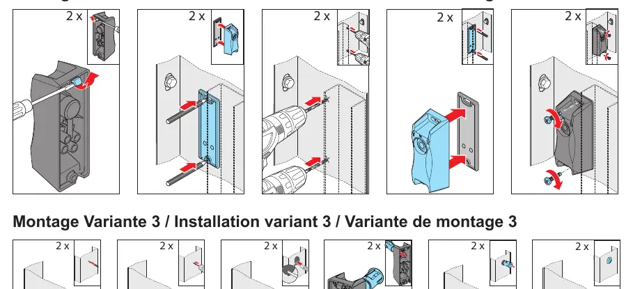
There are three primary mounting variants depending on the frame type and thickness:
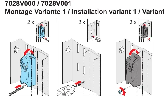
- Variant 1: Standard wall mounting using the provided back cover.
- Variant 2: Mounting using the provided mounting sheet.
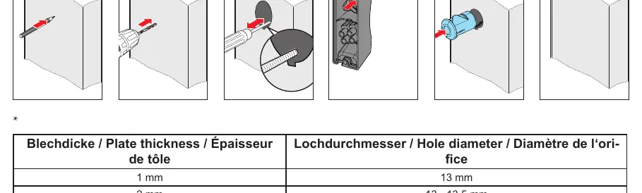
- Variant 3: Flush mounting into the frame.
Refer to the plate thickness table for hole diameter requirements: 1 mm plate requires a 13 mm hole; 2-3 mm plates require a 13-13.5 mm hole.
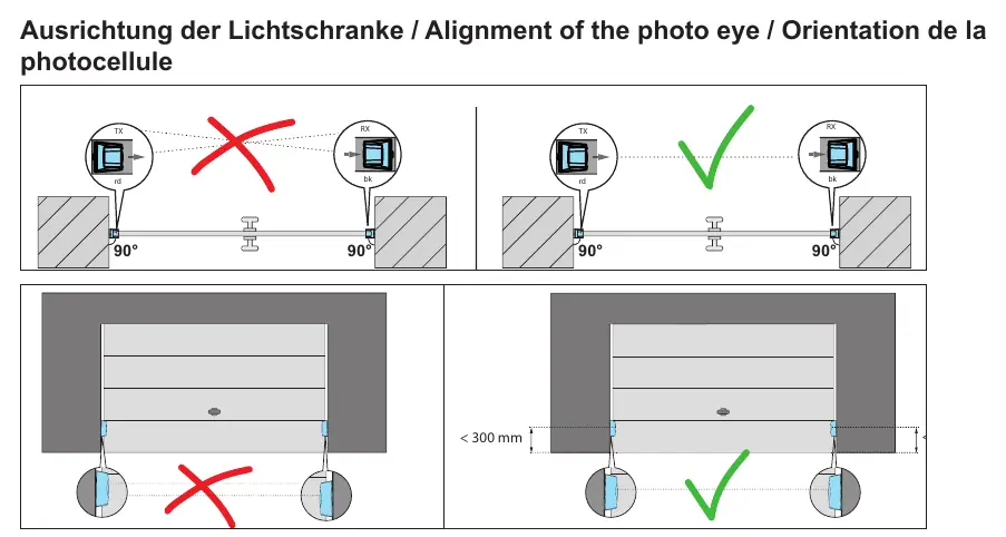
Alignment
Proper alignment is critical for operation. The transmitter (TX) and receiver (RX) must be positioned directly opposite each other at a 90-degree angle. Ensure the installation height is strictly below 300 mm from the ground.
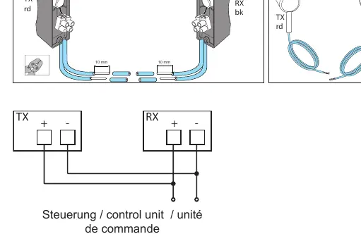
Wiring
The system uses a 2-wire connection. Connect the TX and RX units to the control unit as shown in the wiring diagram. Ensure wires are stripped correctly (10 mm) before insertion into the terminals.
Practical help
Common problems
Photo eye not detecting
Ensure the transmitter and receiver are aligned at exactly 90 degrees and the installation height is below 300 mm.
Installation failure
Installation must be performed by qualified experts only.
Before use
- Verify the installation height is less than 300 mm.
- Ensure the photo eye is aligned at 90 degrees.
- Check that the cable cross-section does not exceed 0.5 mm².
- Confirm the environment temperature is between -20°C and 60°C.
- Ensure wires are stripped to 10 mm for connection.
Specs in practice
- Protection type
- IP 67 rating indicates the device is dust-tight and protected against immersion in water.
Images and diagrams
- Wiring diagram shows the connection of TX and RX units to the control unit.
- Installation variants illustrate mounting methods for different frame thicknesses.
Model compatibility
- Requires professional installation.
- Compatible with 2-wire control systems.

Manual page author
Emily Carter
User documentation editor
Prepares concise manual descriptions and highlights the most useful setup, operation, and maintenance information for readers.