Home / Garage Door Openers
Installation Manual for Sommer 7023 Photo Eye
Quick installation guide for the Sommer 7023 2-wire photo eye. Includes wiring diagrams, technical specifications, and mounting instructions for proper setup.
Quick answers from the manual
Quick answer
- The Sommer 7023 is a 2-wire photo eye system with an 8-meter range, designed for connection to a compatible control unit via COM and SIGNAL terminals. p. 1, 2
Key actions
- Mount the TX and RX units with a clear line of sight, ensuring they are within 8 meters of each other. p. 1
- Connect the photo eye to the COM and SIGNAL terminals of the control unit. p. 2
Problems and fixes
Device not functioning
Check alignment and wiring connections to the control unit.
p. 1, 2Technical specifications
| Parameter | Value | Meaning | Pages |
|---|---|---|---|
| Range | 8 m | Maximum operating distance | p. 1 |
| Bus Voltage | 20 V - 30 V | Required operating voltage | p. 1 |
| IP Rating | IP 44 | Protection class | p. 1 |
Where to find it in the PDF
- Technical Data and Mounting p. 1
- Electrical Connection p. 2
Table of contents
Manual images
Click an image to enlargeQuick guide from the manual
This document provides installation and connection instructions for the Sommer 7023 2-wire photo eye. The device is designed for use with compatible control units and requires a 2-wire connection. Ensure the installation environment meets the specified temperature and distance requirements before proceeding.
Technical specifications
- Operating Range: 8 meters
- Temperature Range: -20°C to 60°C
- Bus Voltage: 20V to 30V
- Current Consumption: Max 20 mA
- Protection Class: IP44
Installation
The installation process involves mounting the transmitter (TX) and receiver (RX) units. Follow these steps:
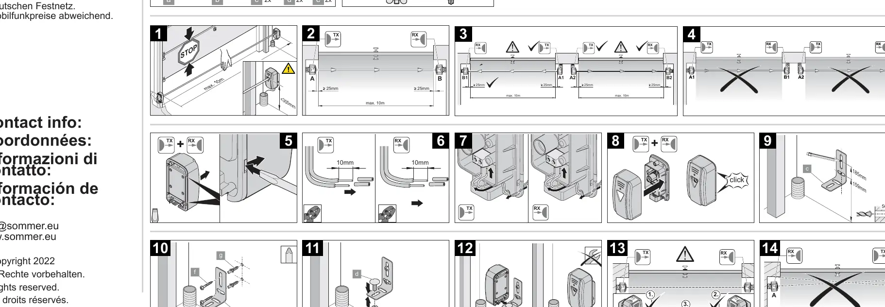
- Ensure the mounting surface is flat and stable.
- Maintain a maximum distance of 10 meters between the TX and RX units (though the effective range is 8 meters).
- Mount the units at a height that allows clear line-of-sight.
- Use the provided mounting hardware to secure the units.
- Ensure the units are aligned correctly to allow the infrared beam to pass between them.
- The installation sequence (steps 1-14) details the physical mounting, cable routing, and final alignment.
Electrical connection
The Sommer 7023 uses a 2-wire connection system. Connect the wires to the control unit as follows:
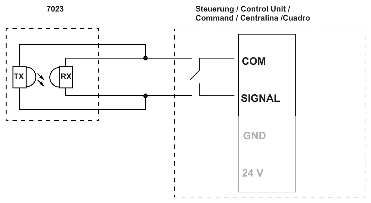
- Connect the photo eye to the COM and SIGNAL terminals on your control unit.
- Ensure the wiring is secure and follows the 2-wire configuration diagram provided in the manual.
- Verify that the control unit provides the required bus voltage (20V - 30V).
Practical help
Common problems
Photo eye not detecting
Check the alignment between the transmitter (TX) and receiver (RX). Ensure there are no obstructions in the beam path.
Device not powering on
Verify that the bus voltage from the control unit is between 20V and 30V.
Before use
- Verify the mounting surface is flat and suitable for the units.
- Ensure the distance between TX and RX is within the 8m operating range.
- Confirm the control unit supports a 2-wire photo eye connection.
- Check that the wiring is connected to the correct COM and SIGNAL terminals.
- Ensure the environment temperature is between -20°C and 60°C.
Images and diagrams
- The wiring diagram illustrates the connection of the TX and RX units to the control unit's COM and SIGNAL terminals.
- The mounting diagrams (steps 1-14) show the physical installation process, including cable routing and unit alignment.
Model compatibility
- Designed for 2-wire systems.
- Compatible with control units providing 20-30V bus voltage.

Manual page author
Michael Turner
Technical manual editor
Reviews PDF manuals for structure, safety notes, and practical product details so readers can find the right information quickly.