Home / Garage Door Openers
User Manual for Craftsman 139.53975SRT1 Garage Door Opener
Comprehensive user manual for the Craftsman 139.53975SRT1 and 139.53962SRT1 garage door openers. This guide includes detailed instructions for assembly, installation, safety adjustments, remote programming, and troubleshooting.
Table of contents
Manual images
Click an image to enlargeQuick guide from the manual
This manual provides instructions for the installation, operation, and maintenance of the Craftsman 1/2 HP Garage Door Opener (Models 139.53975SRT1 and 139.53962SRT1). Before beginning, ensure the garage door is properly balanced, locks are disabled, and all ropes are removed. The opener must be installed at least 7 feet above the floor.
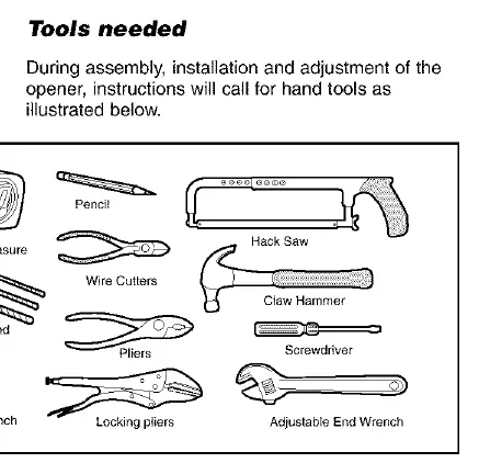
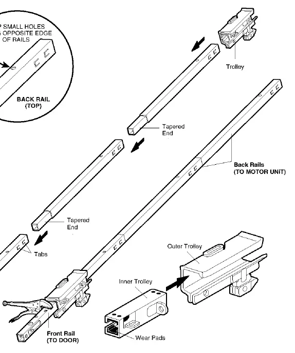
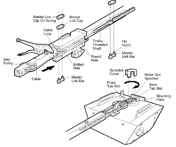
Assembly
The assembly process involves preparing the rail, installing the trolley, and attaching the chain/cable system. Ensure the rail sections are aligned correctly and the trolley is installed before fastening the rail to the motor unit. The chain tension should be adjusted so it is approximately 1/2 inch above the base of the rail at its midpoint.
Installation
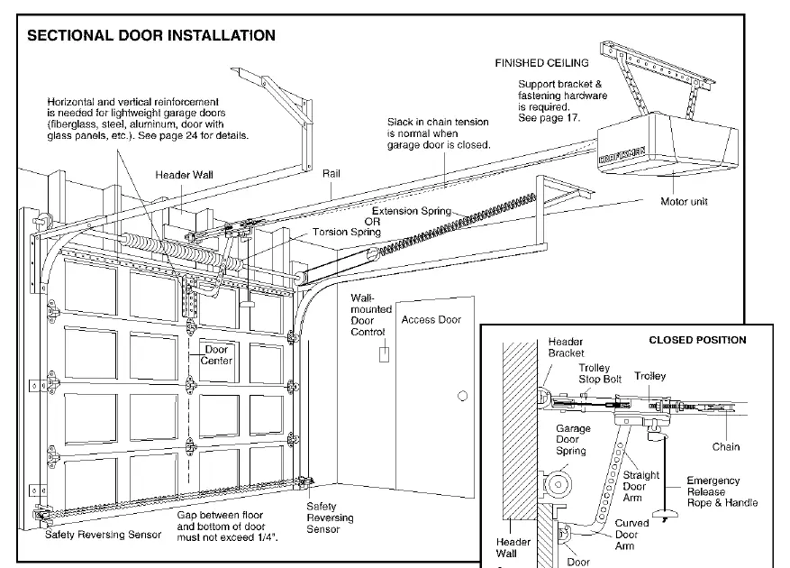
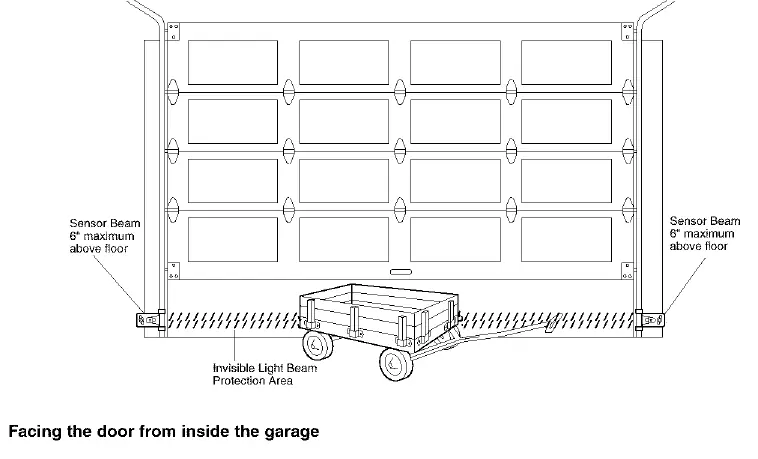
Installation requires mounting the header bracket, positioning the opener, hanging the motor unit, and installing the door control and safety reversing sensors. The safety reversing sensors must be installed no higher than 6 inches above the garage floor and aligned so the sending and receiving eyes face each other. The door bracket must be securely fastened to the door, and the door arm connected to the trolley.
Adjustment
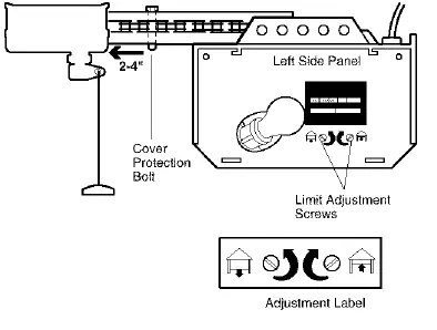
After installation, you must adjust the travel limits and force settings. The travel limits regulate where the door stops when opening and closing. The force settings control the power required to move the door. Important: After any adjustment, you must test the safety reversal system by placing a one-inch board on the floor; the door must reverse upon striking the obstruction.
Operation and Programming
The opener can be operated via the wall-mounted door control or hand-held remote controls. To program additional remotes, use the 'learn' button on the motor unit or the premium control console. The manual also details how to set up a keyless entry PIN and how to operate the door manually in case of power failure using the emergency release handle.
Maintenance
Perform monthly checks on the door balance and safety reversal system. Twice a year, check the chain tension. Once a year, lubricate door rollers, bearings, and hinges. Do not lubricate the door tracks.
Manufacturer information
CRAFTSMAN
Practical help
Common problems
Opener does not operate from door control or remote
Check power supply, ensure door locks are disabled, check for broken springs, or wait 15 minutes if the overload protector has tripped.
Remote control has short range
Change the location of the remote in your car, ensure the antenna on the motor unit extends fully downward, or consider an antenna extender kit.
Door reverses for no apparent reason
Check safety sensors for obstructions or misalignment, clear ice/snow from the floor, or adjust force settings.
Chain sags or droops
It is normal for the chain to droop slightly when the door is closed. If it returns to normal height when the door is open, no adjustment is needed.
Before use
- Disable all door locks.
- Remove all ropes connected to the garage door.
- Ensure the garage door is balanced and not sticking or binding.
- Verify the gap between the floor and the bottom of the door does not exceed 1/4 inch.
- Ensure the safety reversing sensor is installed and aligned.
Images and diagrams
- Wiring diagram: Shows connections for the door control and safety sensors to the motor unit terminals.
- Parts diagram: Illustrates the rail assembly, motor unit components, and installation hardware.
Model compatibility
- For residential use only.
- Compatible with Security+ remote controls.
- Requires 120V, 60 Hz power source.

Manual page author
David Miller
Documentation analyst
Organizes user manual content into clear summaries, with attention to model details, product context, and everyday usability.