Automotive / Electrical Accessories
Installation Manual for SSV Works 230-RG4-SWE12 Switcher Box Mounting Kit
Complete installation guide for the SSV Works 230-RG4-SWE12 Switcher Box Mounting Kit for Polaris Ranger. Includes parts list, mounting steps for the controller and brain module, and wiring instructions.
Quick answers from the manual
Quick answer
- This manual provides installation instructions for the SSV Works 230-RG4-SWE12 Switcher Box Mounting Kit on 2018-Up Polaris Ranger vehicles. p. 1
Key actions
- Mount the 15-button controller using the RAM mount assembly. p. 3
- Drill holes in the dash pocket for the controller mount and cable. p. 4
- Mount the brain module to the firewall. p. 5
First start
- Plug the 15-button controller into the module before connecting power/ground to the battery. p. 6
Show 1 more answers Show less
Where to find it in the PDF
- Parts Contents p. 2
- Installation p. 3, 4, 5, 6
Table of contents
Manual images
Click an image to enlargeQuick guide from the manual
This manual provides instructions for installing the SSV Works 230-RG4-SWE12 Switcher Box Mounting Kit on 2018-Up Polaris Ranger vehicles. Important: The 15-button controller must be plugged into the module before connecting the power and ground cables to the battery to avoid damage. Refer to the SW-E12 instructions manual for detailed programming procedures.
Parts Contents
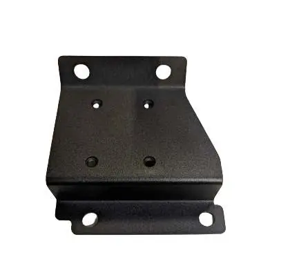
- Ranger SWE-12 Module Mounting Plate [B-A3293]
- Ranger RAM Mount Mounting Plate [B-A3322]
- Push Rivet (x4) [B-HPSR-4]
- M5 Phillips Screw and Flat Washer (x4) [B-S1158]
- 4-40x0.375 Fine Thread Cutting Screw (x4) [B-S3262]
- #12x0.75 Phillips Screw (x4) [B-HP3300]
Tools Needed
- Phillips Screw Driver
- 13mm wrench
- 5/8” and 5/16” Drill Bit
- Drill
Controller RAM Mount Assembly
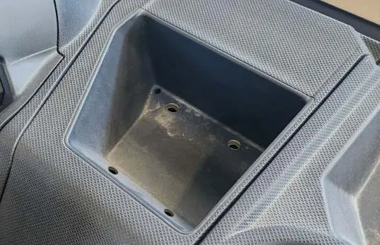
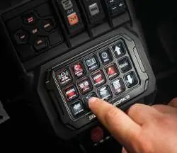

- Attach the RAM Mount ball adapter to the Controller Mounting bracket using the 1 3/8” pan head screw and locknut.
- Attach the Controller Mounting Bracket to the 15-Button Controller using the (4) 4-40x0.75 Thread cutting screws.
- Insert the 15-Button Touch screen with the RAM Mount ball and the RAM Mount base to the Double Socket Arm and tighten the T-knob.
15-Button Controller Installation
- Place the Ranger RAM Mount mounting plate in the dash pocket and mark drill holes on the 4 corner holes.
- Drill (4) holes for the push rivets using a 5/16” drill bit.
- Drill a 5/8” hole in the middle of the dash pocket for the controller cable.
- Insert the 15-button controller cable through the middle hole in the dash pocket.
- Use (4) push-in rivets to secure the Ranger RAM Mount mounting plate to the dash pocket.
- Mount the 15-button with RAM Mount to the mounting plate using (4) M5x16mm Pan-Head screws (B-S2708) included in the ALPHA12 kit.
Brain Module Installation
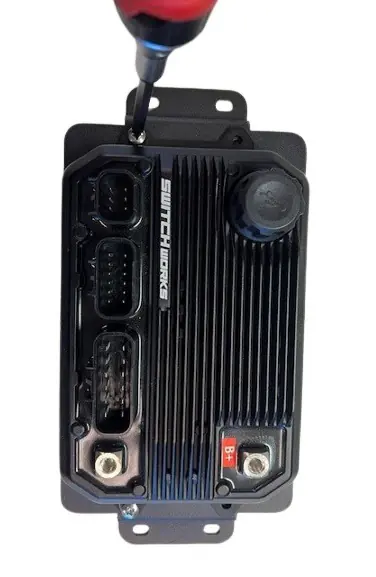
- Mount the ALPHA12 Brain module to the Ranger brain module bracket [B-A3293] using (4) M5x10mm Phillips screws [B-S1158] and washers.
- Use the (4) #12x0.75” self tapping Phillips screws [B-HP3300] to secure the Ranger brain bracket to the firewall below the busbar. Line up the bracket holes to the pre-existing screw bosses.
Wiring and Connection
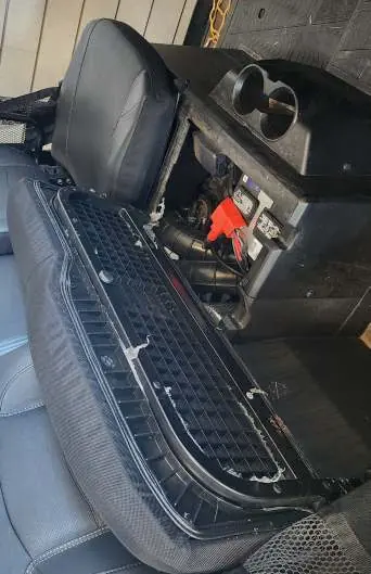
- Run the power and ground wires from the ALPHA12 kit to the battery location. The battery is located under the front passenger seat on 2-door models and under the rear passenger seat in 4-door models.
- Connect the accessories to the High and Low current harnesses and plug the harnesses into the brain module.
- Snap on the terminal cover to the module’s + terminal.
Practical help
Common problems
Controller not responding or system failure
Ensure the 15-button controller is plugged into the module before connecting the power and ground cables to the battery.
Before use
- Verify all parts from the parts list are present.
- Ensure you have a Phillips screwdriver and 13mm wrench.
- Have a 5/16” and 5/8” drill bit ready.
- Identify battery location (under front passenger seat for 2-door, rear passenger seat for 4-door).
Show more Show less
Specs in practice
- 15-Button Controller
- The main interface for the switcher system.
- Brain Module
- The central control unit for the switcher system.
Images and diagrams
- The manual includes diagrams for the RAM mount assembly, dash pocket drilling locations, and brain module mounting points.
Model compatibility
- Compatible with 2018-Up Polaris Ranger models.

Manual page author
Emily Carter
User documentation editor