Automotive / Electrical Accessories
Installation Manual for SSV Works 240-MAVR-PHZ3VTD Maverick R 3-Speaker Audio System
Complete installation guide for the SSV Works 240-MAVR-PHZ3VTD 3-Speaker Audio/RGB System for Can-Am Maverick R. Includes detailed steps for dashboard disassembly, wiring, amplifier mounting, and subwoofer installation.
Quick answers from the manual
Quick answer
- This manual provides step-by-step instructions for installing the SSV Works 240-MAVR-PHZ3VTD 3-Speaker Audio/RGB System in a 2024+ Can-Am Maverick R, including dashboard disassembly, wiring, and component mounting. p. 1, 3, 7, 9
Key actions
- Dashboard disassembly p. 3, 4
- Subwoofer installation p. 7, 8
- Wiring and power connection p. 9, 10, 11
Technical specifications
| Parameter | Value | Meaning | Pages |
|---|---|---|---|
| Amplifier | 1650W | Power rating of the amplifier assembly. | p. 2 |
| Subwoofer | 10 inch | Size of the subwoofer enclosure. | p. 2 |
Show 1 more answers Show less
Where to find it in the PDF
- Parts List p. 2, 4
- Installation Steps p. 3, 12
Table of contents
Manual images
Click an image to enlargeQuick guide from the manual
This installation manual covers the setup of the SSV Works 240-MAVR-PHZ3VTD 3-Speaker Audio/RGB System for the 2024+ Can-Am Maverick R. Before beginning, ensure you have the necessary tools: T30 Torx driver, Phillips screwdriver, pry tool, 3mm and 5mm Allen wrenches, wire cutter, and 10mm, 13mm, and 18mm socket wrenches. Always disconnect the negative battery terminal before starting electrical work.
Parts list
- Under seat 10" Subwoofer
- Speaker Panel Kit (Driver and Passenger Side)
- 1650W Amplifier Assembly
- Amplifier Turn-On Delay Module
- LIT-CC RGB Controller
- Power Pigtail and Zip Ties
Dashboard disassembly
To access the installation areas, follow these steps:
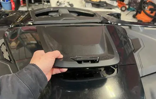
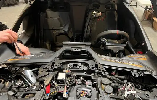
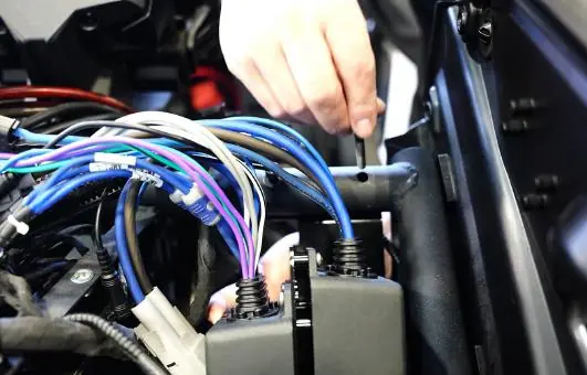
- Use a plastic pry tool to remove the driver and passenger side front trims.
- Remove the front fuse box cover.
- Use a pry tool to remove the left and right side center panel trims.
- Remove the left and right A-pillar trims using a 3mm Allen wrench.
- Remove the left and right side dashboard panels.
- Remove the u-nuts from the factory panels and install them on the new Mav R dash panels.
- Remove the central dashboard.
RGB LED controller installation
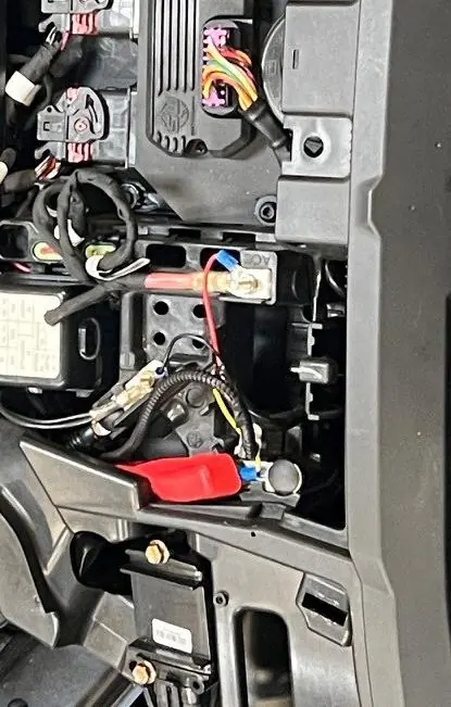
- Install the LIT-CC RGB LED Controller Rocker Switch into an unoccupied rocker switch opening.
- Mount the LIT-CC RGB LED Controller Command Center in the dash, ensuring it is away from moving parts, and secure it with zip ties.
- Tap the power and ground of the LIT-CC to the factory bus bar.
- Plug the LIT-CC controller into the LIT-CC module.
Amplifier installation
- Connect the amplifier turn-on delay module's power and ground wires to the factory bus bar and secure with zip ties.
- Route the turn-on delay output wire toward the steering column.
- Mount the amp bracket next to the power steering motor on the driver side chassis frame using the provided M6-1x45mm socket head screws and washers.
Under seat subwoofer installation
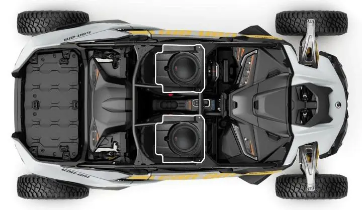
- Remove the driver seat. Use an 18mm socket to remove the right shoulder seat belt retractor mechanism.
- Remove the two 13mm bolts and nuts on the front seat rail.
- Slide the seat forward and remove the rear 18mm seat rail nuts.
- Apply the included foam pad to the flat portion of the bottom reinforcement tube.
- Mount the brackets on the subwoofer enclosure using four M6x12mm hex head bolts and washers.
- Slide the enclosure under the front seat rail mounts and secure it using the front screw holes and two M6x16mm hex head bolts.
Power and speaker wiring
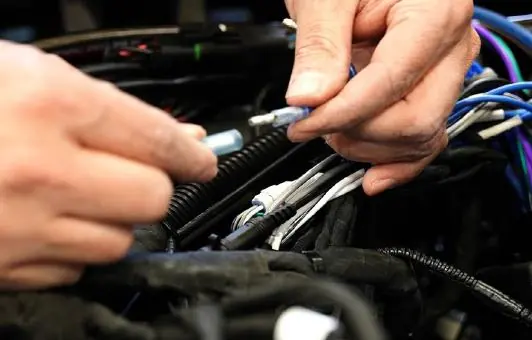
- Remove the battery cover behind the driver seat and disconnect the negative battery terminal.
- Remove the cup holder and center console side panels.
- Run the rear speaker and subwoofer cables along the passenger side of the center console.
- Plug the subwoofer connector into the B-H2702 extension cable.
- Route the power cable along the driver side center console from the battery to the dash.
- Plug the amplifier power connector into the power cable.
- Connect the 8-pin speaker and 2-pin subwoofer input connectors to the factory radio output wiring.
- Connect the amplifier's turn-on bullet connectors to the turn-on delay module output wire.
- Install the fuse holder on the power wire within 18 inches of the battery and install the fuse.
- Connect the power wire to the battery positive and negative posts.
Dash panel assembly
- Insert the speaker bucket grommets into the front dashboard support holes with the "UP" side facing top.
- Plug the audio and RGB connectors of the B-H1385 harness into the dash panel speakers.
- Mount the dash panels onto the dashboard.
- Reverse the disassembly steps to reinstall the center console and other panels.
Practical help
Common problems
Difficulty routing cables
Use zip ties to tidy up the install and ensure cables are routed away from moving parts and seat bolts.
Subwoofer fitment
Ensure the foam pad is applied to the bottom reinforcement tube before sliding the enclosure into place.
Before use
- Verify all parts from the parts list are present.
- Disconnect the negative battery terminal.
- Gather required tools: T30 Torx, Phillips screwdriver, pry tool, 3mm/5mm Allen wrenches, wire cutter, 10mm/13mm/18mm sockets.
- Ensure the vehicle is in Park (P) before starting.
Show more Show less
Specs in practice
- 1650W Amplifier
- The power rating of the included amplifier assembly.
- 10" Subwoofer
- The size of the subwoofer enclosure included in the kit.
Images and diagrams
- Parts list images identify the subwoofer, speaker panels, amplifier, and RGB controller.
- Wiring diagrams illustrate connections to the factory bus bar and battery terminals.
Model compatibility
- Designed specifically for 2024-Up Can-Am Maverick R vehicles.

Manual page author
Emily Carter
User documentation editor