Automotive / Electrical Accessories
Installation Guide for SSV Works 240-TTU3-SWE12 Mounting Kit for Toyota Tundra Gen 3
Step-by-step installation guide for the SSV Works 240-TTU3-SWE12 mounting kit for the Alpha12 Switcher Box in 2022+ Toyota Tundra vehicles. Includes disassembly, drilling, and wiring instructions.
Quick answers from the manual
Quick answer
- This guide provides instructions for installing the SSV Works 240-TTU3-SWE12 mounting kit for the Alpha12 Switcher Box in a 2022+ Toyota Tundra. p. 1
Key actions
- Disassemble overhead console p. 3
- Drill mounting holes p. 4
- Mount brain module p. 6, 7
- Connect power and ground p. 7, 8
First start
- Ensure the 15-button controller is plugged into the module before connecting the power cable to the battery. p. 8
Show 2 more answers Show less
Technical specifications
| Parameter | Value | Meaning | Pages |
|---|---|---|---|
| Drill bit size | 3mm, 16mm | Required for mounting and cable routing | p. 4 |
| Fuseholder distance | Max 18 inches | Distance from ring terminal | p. 8 |
Where to find it in the PDF
- Parts Contents p. 2
- Overhead Console Installation p. 3, 4, 5
- Brain Module Installation p. 6, 7
Table of contents
Manual images
Click an image to enlargeQuick guide from the manual
This document provides instructions for installing the SSV Works 240-TTU3-SWE12 mounting kit for the Alpha12 Switcher Box in 2022+ Toyota Tundra (Gen 3) vehicles. The process involves two main phases: installing the controller in the overhead console and mounting the brain module in the engine bay. Important: The 15-button controller must be plugged into the module before connecting the power cable to the battery.
Parts contents
- Toyota Tundra Overhead Fascia [B-D3306]
- Toyota Tundra Overhead Mounting Bracket [B-D3307]
- Toyota Tundra ALPHA12 Brain Mount Bracket [B-MB3365]
- #7-19x3/4” Phillips Screws (x7) [B-S1656]
- M5x10 Pan Head Screws (x4) [BS1158]
- 4-40x.375 Thread Cutting Screws (x4) [B-S3262]
- M6x12mm Hex Head Bolt [B-S2780]
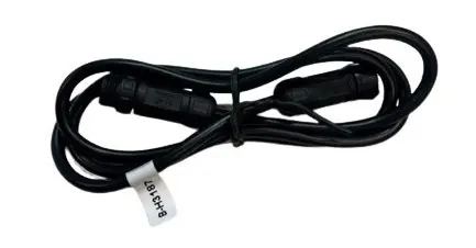
- 4-Pin Extension Cable, 6 ft.
- Zip tie and zip tie panel tree snap
Tools needed for installation
- Phillips Screw Driver
- 3mm and 16mm Drill Bit
- Drill
- Pry Tool
- Pick Tool
- 10mm, 12mm & 13mm Socket Wrench
Overhead console disassembly
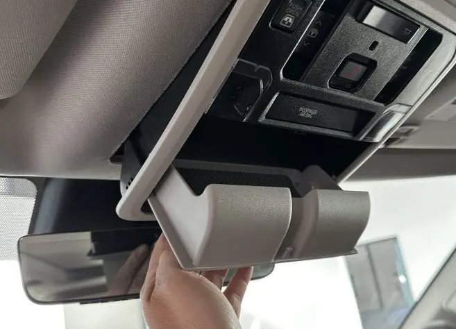
- Use both hands to grab the back edge of the overhead console (closest to the windshield) and pull down firmly until the back snaps loose.
- Slide the console forward towards the windshield.
- Note that the console is hooked onto the headliner with 2 tabs; disconnect the harness.
- Open the sunglass holder and use a pry tool to unsnap the left side.
- Insert a pick tool into the 3 screw posts to mark drill points.
Controller installation
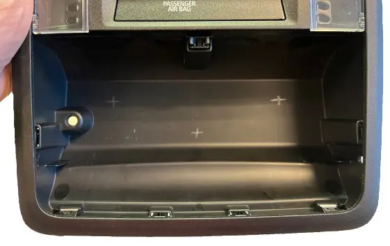
- Mark the drill guides and drill 3 holes using a 3mm drill bit.
- Drill a 16mm hole for the controller cable connector.
- Assemble the Tundra fascia to the mounting bracket using (4) #7-19x3/4” Phillips screws (B-S1656).
- Mount the ALPHA12 controller to the Tundra fascia using (4) 4-40x.375 thread cutting screws (B-S3262).
- Insert the cable through the drilled hole and place the controller/bracket in the sunglass holder cavity.
- Flip the console upside down and secure the bracket using (3) #7-19x3/4” Phillips screws (B-S1656).
- Run the controller cable along the headliner towards the driver side A-pillar and down to the firewall. Use the 6ft extension cable to reach the brain mount location.
- Reinstall the A-pillar trim and overhead console.
Brain module installation
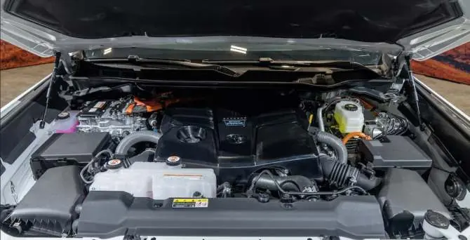
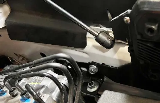
- The brain module is mounted on the driver side fender above the fusebox.
- Mount the ALPHA12 brain module to the brain bracket (B-MB3366) using (4) M5x10mm pan head screws (B-S1158).
- Remove the front bolt of the ABS pump bracket using a 12mm wrench.
- Remove the horn bracket bolt using a 10mm wrench.
- Remove the hood release cable from the cable clamp.
- Position the horn and Alpha12 brackets and fasten using the horn bracket bolt (do not tighten yet).
- Put the upper Alpha12 bracket tab behind the factory hood lift support shock mount and fasten using the supplied M6x12mm screw (B-S2780) (do not tighten yet).
- Position the bottom left tab of the Alpha12 bracket to the ABS pump bracket and fasten using the factory bolt. Tighten all 3 mounting bolts.
- Connect accessories to the High and Low current harnesses and plug them into the brain module.
- Connect the ground wire from the brain module to the factory grounding point on the driver side fender.
Wiring and power connection
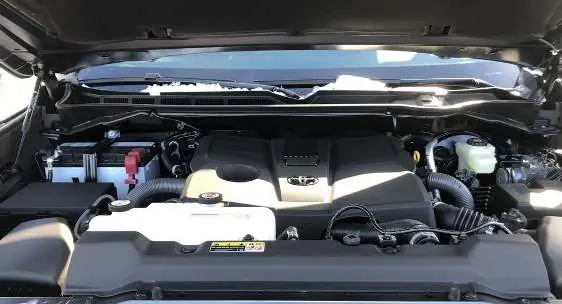
- Run the power wire from the brain module along the firewall towards the battery.
- Cut the power cable and install the provided fuseholder no more than 18” away from the ring terminal.
- Connect the power cable to the battery.
Practical help
Common problems
Controller not working after installation
Ensure the 15-button controller is plugged into the module before connecting the power cable to the battery.
Difficulty mounting brain module
Ensure the horn and Alpha12 brackets are positioned correctly before tightening the horn bracket bolt.
Before use
- Verify all parts are present (fascia, brackets, screws, cables)
- Gather required tools (Phillips screwdriver, drill, 3mm/16mm bits, pry tool, 10/12/13mm sockets)
- Ensure vehicle is off and battery is disconnected before starting electrical work
Show more Show less
Specs in practice
- Drill bit size (holes)
- 3mm for mounting holes, 16mm for cable connector
- Fuseholder placement
- No more than 18 inches away from the ring terminal
Model compatibility
- Designed specifically for 2022+ Toyota Tundra (Gen 3)

Manual page author
Emily Carter
User documentation editor