Automotive / Battery Chargers
Stetsom 1200EQ Automotive Amplifier User Manual
Quick guide for the Stetsom 1200EQ automotive amplifier. Includes installation instructions, wiring diagrams, audio control settings, LED indicator diagnostics, and troubleshooting tips.
Table of contents
Manual images
Click an image to enlargeQuick guide from the manual
This manual provides essential instructions for the installation and operation of the Stetsom 1200EQ automotive amplifier. Always perform installations with the product turned off and by a qualified professional. Ensure a fuse or circuit breaker is installed as close to the battery as possible to protect against overcharging.
Audio controls
The amplifier features several controls to adjust the audio output:
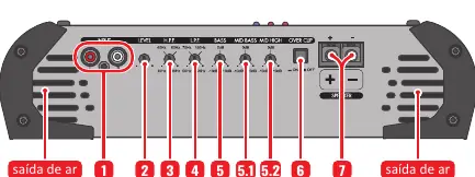
- INPUT: Connect to the radio/player using high-quality shielded RCA cables.
- LEVEL: Adjusts the signal level at the amplifier input.
- HIGH PASS FILTER (H.P.F.): Selects the initial frequency (10Hz to 700Hz).
- LOW PASS FILTER (L.P.F.): Selects the final frequency (50Hz to 25KHz).
- BASS: Variable bass boost (0 to +10dB) at 45Hz.
- MID BASS: Variable boost (0 to +10dB) at 270Hz.
- MID HIGH: Variable boost (0 to +10dB) at 2KHz.
- OVER CLIP: When enabled, the CLIP LED indicates distortion at 15% higher power.
Power connections
The power input panel includes:
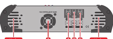
- COOLER: Fan speed is controlled by the audio volume.
- POSITIVE POWER CONNECTOR: Connect to the positive battery terminal using a minimum 6 AWG cable with a 40A fuse/circuit breaker.
- REMOTE CONNECTOR (REM): Connect to the remote output of the radio/player using a minimum 18 AWG cable for automatic activation.
- NEGATIVE POWER CONNECTOR: Connect to the negative battery terminal using a minimum 6 AWG cable.
LED indicators and protection system
The amplifier includes a smart protection system. If the PROT LED blinks, it indicates a fault:

- 1x Blink: Short circuit or output overload. Check speaker cables and impedance.
- 2x Blinks: Excessive temperature (approx. 90°C). Ensure ventilation and check for obstructed coolers.
- 3x Blinks: Supply voltage less than 9V. Check battery or power supply.
- 4x Blinks: Supply voltage greater than 16V. Check battery or power supply.
Installation
Follow these guidelines for proper installation:
- Use recommended cable gauges: 6 AWG for power, 18 AWG for remote, and 11 AWG for speakers.
- Route installation cables away from the vehicle's original wiring to prevent interference.
- Ensure the amplifier is installed in a firm, ventilated, and dry location.
- Use a star connection for grounding to avoid ground loops.
Troubleshooting
If you encounter issues, check the following:
- Amplifier does not turn on: Verify cable connections, check fuses/circuit breakers, and ensure battery charge is sufficient.
- No sound: Check RCA plugs and speaker cables; ensure the LEVEL control is not set to minimum.
- Distorted sound: Lower the level and re-adjust. Play music at 80% volume on the radio, then increase the amplifier LEVEL until the CLIP LED flashes, then back off slightly.
- Lack of bass: Check for reversed speaker polarities (out-of-phase).
Technical specifications
Key specifications include:
- Minimum Output Impedance: 1 Ohm or 2 Ohms (model dependent).
- Frequency Response: 10Hz ~ 25KHz @ 8 Ohms.
- Supply Voltage: 9.5V ~ 15V.
- Signal to Noise Ratio: >90dB.
Practical help
Common problems
Amplifier does not turn on
Verify that all cables are connected correctly and have good electrical contact. Check if fuses or circuit breakers are blown or defective. Ensure the battery charge is sufficient.
No sound
Check that speaker cables and RCA plugs are connected correctly and not defective. Ensure the LEVEL control is not set to the minimum position.
PROT LED flashing
Check for short circuits or output overload. Ensure ventilation is not blocked and the amplifier is not overheating. Verify supply voltage is between 9V and 16V.
Distorted sound
The speakers may be overloaded. Lower the level and re-adjust the gain by setting the radio volume to 80% and increasing the amplifier LEVEL until the CLIP LED flashes, then backing off.
Lack of bass
Check if speaker cables have reversed polarities (+ and -), which causes out-of-phase sound.
Before use
- Ensure all product connections are made with the product turned OFF.
- Install a fuse or circuit breaker as close to the battery as possible.
- Use the recommended cable gauges (6 AWG for power, 18 AWG for remote, 11 AWG for speakers).
- Route installation cables away from the vehicle's original wiring to avoid interference.
- Perform the installation in a firm, ventilated, and dry place.
- Installation must be done by a qualified professional.
Specs in practice
- Minimum Output Impedance
- The lowest resistance load the amplifier can handle (1 Ohm or 2 Ohms depending on the specific version).
- Supply Voltage
- The operating voltage range (9.5V to 15V DC) required for the amplifier to function.
- Signal to Noise Ratio
- Indicates the clarity of the audio signal; >90dB is a good standard for audio quality.
- Frequency Response
- The range of frequencies the amplifier can reproduce (10Hz to 25KHz).
Images and diagrams
- The control panel diagram shows the input RCA jacks, level control, filters (HPF/LPF), bass/mid boost knobs, and speaker output terminals.
- The power input diagram illustrates the cooling fan, positive/negative power terminals, and the remote turn-on connector.
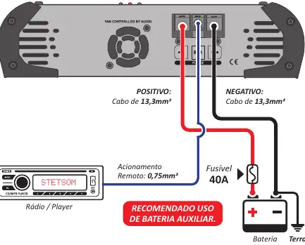
- The installation wiring diagram shows the connection path from the radio/player to the amplifier, and from the amplifier to the battery (with fuse) and speakers.
Model compatibility
- Requires a 40A fuse or circuit breaker.
- Power cables must be at least 6 AWG (13.3mm²).
- Remote cable must be at least 18 AWG (0.75mm²).
- Speaker cables must be at least 11 AWG (4mm²).

Manual page author
Michael Turner
Technical manual editor
Reviews PDF manuals for structure, safety notes, and practical product details so readers can find the right information quickly.