Automotive / Car Audio
Owner's Manual for SounDigital 1200.4 EVOPS Amplifier
Quick guide for the SounDigital 1200.4 EVOPS amplifier. Includes installation steps, wiring diagrams, gain setting procedures, crossover configuration, and technical specifications.
Table of contents
Manual images
Click an image to enlargeQuick guide from the manual
This manual provides essential instructions for the SounDigital 1200.4 EVOPS amplifier. Key operations include proper electrical dimensioning, secure installation, and precise gain/crossover configuration. Always disconnect the negative battery terminal before starting any installation work. Ensure your battery voltage is between 12.6V and 14.4V for optimal performance.
Product Overview
The SounDigital 1200.4 EVOPS is a high-efficiency Class D amplifier designed for power sports applications. It features a compact, robust design with an IP64 rating, making it resistant to moisture, water splashes, and dust. It utilizes DTM (Dynamic Thermal Management) and an I-POWER supply for improved efficiency.
Safety Instructions
- Always disconnect the negative (-) battery terminal before installation to prevent fires or injuries.
- Use OFC (Oxygen Free Copper) cables for installation.
- Mount the amplifier in a dry, ventilated location, avoiding metallic surfaces to prevent ground loops.
- Ensure the fuse or circuit breaker is installed within 30cm (1 foot) of the battery.
- Wear appropriate PPE (gloves, safety glasses) during installation.
- The amplifier can reach temperatures over 60°C/140°F; allow it to cool before touching.
Assembling and Disassembling the Plastic Seals
The amplifier includes plastic seals to protect connectors. To disassemble, squeeze the assembled flexible plastic seals and pull them out. To assemble, hold the seals and fit them into their specific housing, ensuring each connector has its corresponding seal and is perfectly fitted.
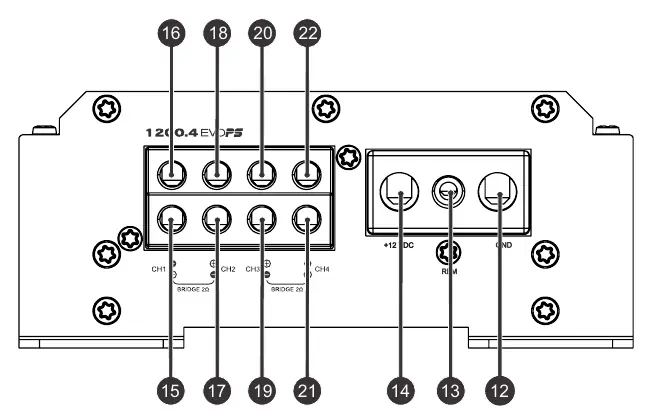
Panels Description
The amplifier features two main panels:
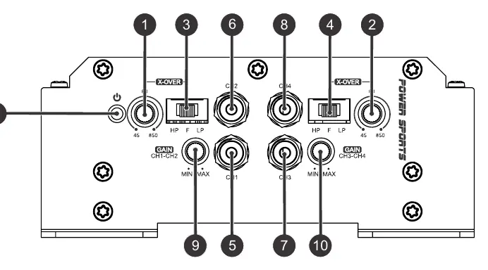
- Audio inputs and controls: Includes RCA connectors for audio input, variable gain controls for CH1/CH2 and CH3/CH4, and crossover switches (Low Pass, Full, High Pass).
- Power inputs and audio outputs: Includes terminals for +12VDC, Remote (REM), and Ground (GND), along with speaker output terminals for channels 1 through 4.
Installation
Follow these steps for a successful installation:


- Mount the amplifier securely.
- Install power cables from the battery to the fuse holder/circuit breaker, then to the amplifier.
- Connect the ground cable to the battery negative or vehicle chassis (ensure the connection point is free of paint).
- Connect signal input cables (RCA) away from power cables.
- Connect speaker output cables, respecting positive (+) and negative (-) polarities.
- Connect the remote cable to the REM terminal.
- Verify all connections, then reconnect the battery ground and insert fuses.
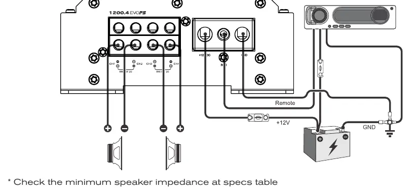
Wiring Diagrams
The manual provides specific wiring diagrams for different configurations:
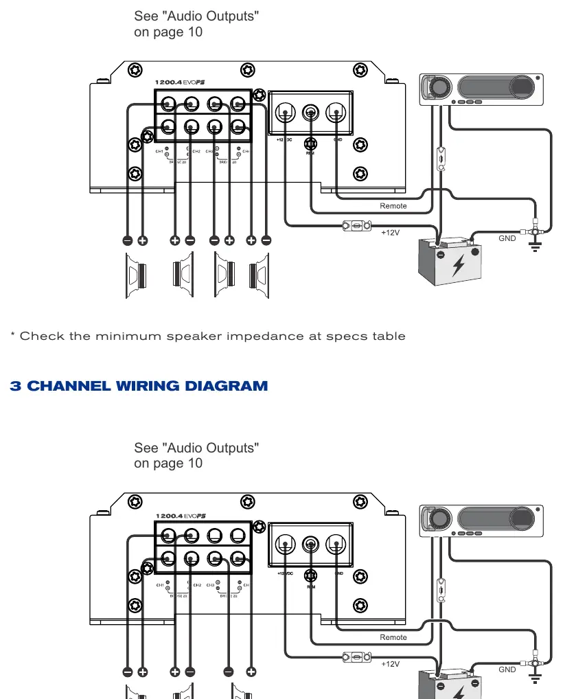
- Four channels: Standard setup for four speakers.
- Three channels: Mixed setup.
- Two channels: Bridged setup.
Always check the minimum speaker impedance in the technical specifications table before connecting speakers.
Gain Setting
To set the gain correctly:
- Turn the gain control all the way down.
- Disconnect output cables.
- Turn off all audio processing (EQ, bass, treble).
- Set source unit volume to 3/4 of full volume.
- Set crossover switch to 'F' (Full).
- Use a 60Hz sine wave test tone.
- Connect an AC voltmeter to the speaker outputs.
- Increase gain until the target voltage (specified in the manual's chart) is reached.
- Turn off the source unit and reconnect speakers.
Crossover Setup
The crossover allows you to filter frequencies:
- F (Full): All frequencies are reproduced.
- LP (Low Pass): Set the variable control between 45Hz and 850Hz to cut high frequencies.
- HP (High Pass): Set the variable control between 45Hz and 850Hz to cut low frequencies.
Technical Specs
- Operating Voltage: 8V - 16V.
- Frequency Response: 5Hz - 22kHz.
- Input Sensitivity: 0.2V - 4V.
- SNR: 88dB (2Ω model) / 91dB (4Ω model).
- Recommended Battery: 70Ah.
Practical help
Common problems
Amplifier does not turn on
Check the remote cable connection, ensure battery voltage is between 12.6V and 14.4V, and verify the fuse/circuit breaker status.
Noise or ground loop interference
Ensure the ground cable is as short as possible and connected to a clean, paint-free chassis point or battery negative. Avoid mounting on metallic surfaces.
Distorted sound
Verify gain settings using the voltmeter procedure. Ensure source unit volume is at 3/4 and all EQ/processing is turned off during setup.
Before use
- Disconnect the negative battery terminal before starting.
- Ensure battery voltage is between 12.6V and 14.4V.
- Use OFC (Oxygen Free Copper) cables.
- Install fuse/circuit breaker within 30cm (1 foot) of the battery.
- Verify minimum speaker impedance (2Ω or 4Ω depending on model).
- Wear safety glasses and gloves.
Specs in practice
- Operating Voltage
- The DC voltage range (8V-16V) required for the amplifier to function.
- Input Sensitivity
- The range of input signal voltage (0.2V-4V) the amplifier can accept.
- Damping Factor
- Measures the amplifier's ability to control speaker cone movement (200 @ 100Hz).
Images and diagrams
- Wiring diagrams show connections for 4, 3, and 2-channel setups.
- Gain setting procedure uses a 60Hz sine wave and AC voltmeter to match output voltage.
- Crossover setup diagram illustrates the frequency cut-off points for LP, HP, and Full modes.
Model compatibility
- Requires 16mm² (5 AWG) power and ground cables.
- Requires 2x2mm² (12 AWG) speaker cables.
- Minimum impedance varies by model (check specs table for 2Ω or 4Ω).

Manual page author
Emily Carter
User documentation editor
Prepares concise manual descriptions and highlights the most useful setup, operation, and maintenance information for readers.