Home Appliances / Cookers & Ranges
Installation Instructions for Stoves Richmond 100/110cm Electric Induction Cooker
Comprehensive installation guide for the Stoves Richmond 100/110cm Electric Induction Cooker. This manual covers safety requirements, levelling procedures, electrical connection diagrams, and clearance specifications.
Table of contents
Manual images
Click an image to enlargeImportant Installation Information
This appliance must be installed by a competent person who is a member of a 'Competent Person Scheme' to ensure compliance with regulations. The appliance must be earthed. Before installation, ensure all packaging is removed and accessories (shelves, trays, air fry basket) are washed in hot soapy water. It is recommended to run the ovens and grill for a short period before first use to burn off manufacturing residues.
Before Installation
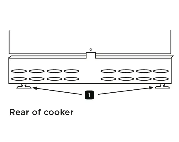
The cooker is equipped with levelling feet. Place a spirit level on a baking sheet on an oven shelf to check the level. Adjust the feet at the front and rear as necessary. For worktop heights between 900-930mm, use the supplied locknuts. If the worktop is lower than 900mm, remove one locknut from each foot.
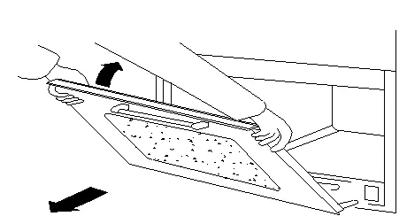
To adjust the rear wheels, open the lower doors. Use a flat-headed screwdriver through the circular holes in the lower front frame. Note: On 100cm and 110cm models, you must remove the bottom-right slow cook compartment door to access the bottom-right circular hole.
Fitting the Decorative Cover Plinth
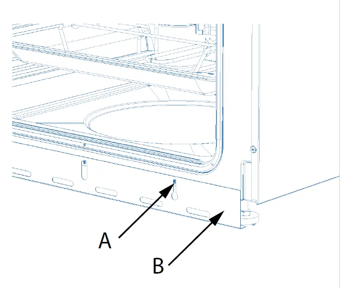
If the cooker is raised and the feet are visible, attach the decorative plinth. Release the screws (A) by a few turns, align the keyway slots in the plinth (B) with the screws, adjust to the desired height, and tighten the screws by hand. Do not use power tools.
Fitting a Towel Rail
Applicable to 90cm, 100cm, and 110cm models. Align the towel rail holes with the fascia panel. Use the provided M6 screws and allen key. Insert longer screws into the upper hole (A) and shorter screws into the lower hole (B). Ensure the rail is flush with the fascia but do not over-tighten.
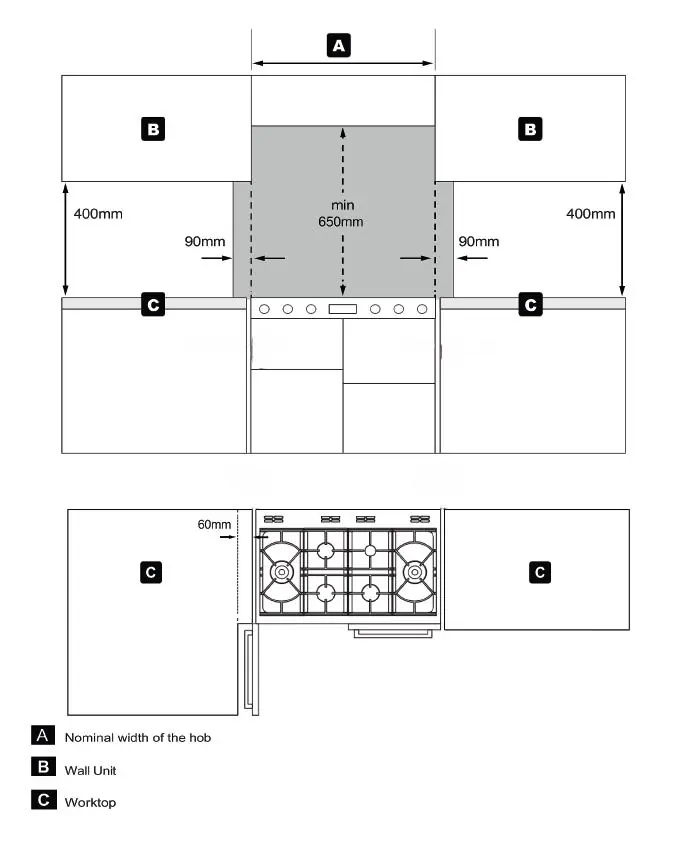
Dimensions & Clearances
Maintain a minimum clearance of 650mm above the hob for any shelf, overhang, or cooker hood. If the appliance has a side-opening door, a 60mm side clearance is recommended if placed next to a wall or side cabinets. Keep the area above and to the sides of the hob clear of combustible materials for 90mm horizontally and 400mm vertically.
Connecting to the Electricity Supply Terminal Block
The appliance must be connected to a switch providing all-pole disconnection with a minimum contact separation of 3mm. Use a suitable flexible cable capable of withstanding a temperature rise of at least 70°C.
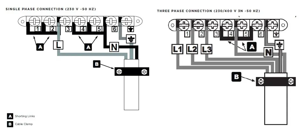
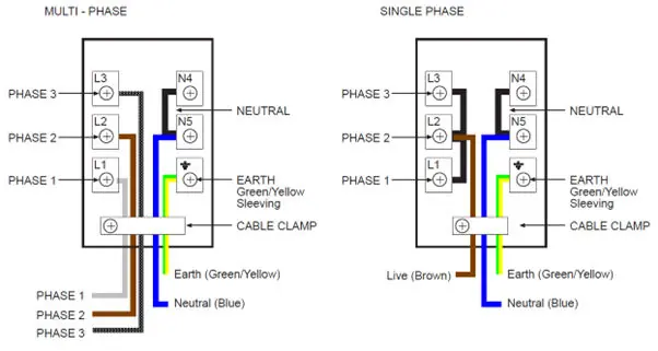
Single-phase connection: Place brass connecting bars between L1 + L2 + L3. Link the mains supply phase live wire to the L2 terminal.
Multi-phase connection: Remove the brass connecting bars from the live terminals and connect the 3 phases to L1, L2, and L3 respectively. Leave neutral connecting bars in place.
Commissioning
Check the clock programmer and minute minder functions. Open the main oven door, turn the control knob to the defrost setting, and verify that the oven light and convection fan activate. If the cooker does not perform correctly, inform the customer and place a warning notice on the unit.
Manufacturer information
Stoves
Practical help
Common problems
Cooker height adjustment issues
Use levelling feet; remove locknuts if the worktop is lower than 900mm.
Cannot access rear wheel adjustment hole
On 100cm/110cm models, remove the bottom-right slow cook compartment door.
Electrical connection errors
Ensure shorting links are correctly configured for single-phase (1-2, 2-3, 4-5, 5-6) or removed for multi-phase.
Before use
- Remove all packaging and wrapping from the appliance.
- Wash oven shelves, baking tray, air fry basket, grill pan, and trivet in hot soapy water.
- Ensure the appliance is earthed.
- Verify that the electrical supply matches the technical data on the rating label.
- Run the ovens and grill for a short time to burn off manufacturing residues.
Specs in practice
- Electrical Supply
- 230-400V ~3N ~ 50 Hz.
- Minimum Hood Clearance
- 650mm above the hob surface.
- Side Clearance
- 60mm recommended for side-opening doors.
Images and diagrams
- Wiring diagrams illustrate the correct terminal bridging for single-phase vs. multi-phase power.
- Levelling diagram indicates the location of feet at the rear of the cooker.
Model compatibility
- Installation must be performed by a member of a 'Competent Person Scheme'.
- Suitable for 100cm and 110cm Richmond range cookers.

Manual page author
Emily Carter
User documentation editor
Prepares concise manual descriptions and highlights the most useful setup, operation, and maintenance information for readers.