Home Appliances / Cookers & Ranges
Installation Instructions for Stoves Richmond 110/100cm Dual Fuel Cooker
A comprehensive installation guide for the Stoves Richmond 110/100cm Dual Fuel Cooker. Includes safety regulations, electrical and gas connection procedures, levelling, and technical specifications.
Table of contents
Manual images
Click an image to enlargeQuick guide from the manual
This appliance must be installed by a competent person in accordance with current regulations. Before installation, ensure the local gas distribution conditions (gas type and pressure) are compatible with the appliance. If you smell gas, do not attempt to light the appliance, do not touch electrical switches, and contact your gas supplier immediately. The appliance must be earthed.
Before installation
Ensure all packaging and wrapping are removed. It is recommended to wash oven shelves, baking trays, and grill pans in hot soapy water before first use. To level the cooker, place a spirit level on a baking sheet on an oven shelf and adjust the levelling feet at the front and rear. If the levelling feet are visible, a decorative cover plinth can be attached using the provided screws.
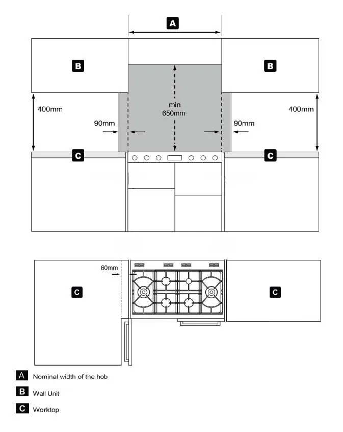
Dimensions and clearances
No shelf or combustible material should be closer than 650mm above the hob. If the appliance has a side-opening door, a side clearance of 60mm is recommended to allow the door to fully open. A side clearance of 90mm is required above the hob level up to a height of 400mm. The cooker must be fitted flush to the base units. Stability devices (chains and wall hooks) must be installed to prevent tipping.
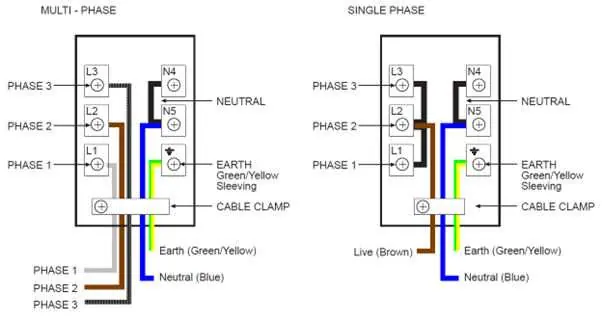
Connecting to the electricity supply terminal block
The appliance must be connected by a competent person. For all connections, leave the connecting bars on the neutral terminals. For single-phase connections, place brass connecting bars between L1, L2, and L3, and connect the live wire to the L2 terminal. For multi-phase connections, remove the brass connecting bars from the live terminals and connect the three phases to L1, L2, and L3 respectively. Ensure the appliance is fitted to a switch providing all-pole disconnection with a minimum contact separation of 3mm. Do not use power tools on terminal block screws.
Connect to the gas supply
The gas inlet is a 1/2 inch BSP parallel internal connection at the rear-top right-hand corner. Use a flexible connector between 900mm and 1125mm in length. Ensure the connector does not come into contact with the vertical oven flue tubes at the rear. After installation, verify all connections are gas sound.
Commissioning
All burners have fixed aeration. To light a hob burner, press and turn the knob to 'FULL ON', hold for 15 seconds. If it fails to light, release and wait one minute before retrying. Check the oven light and convection fan by turning the main oven control to the defrost setting. Always turn knobs to 'OFF' after use.
Technical data
The cooker is configured for Natural Gas and is suitable for conversion to LPG (conversion kit part number 094112400). Operating pressure is 20mbar for Natural Gas and 30mbar for LPG. The appliance class is Class 1 (freestanding).
Manufacturer information
Stoves
Practical help
Common problems
Gas smell
Do not try to light any appliance, do not touch electrical switches, and contact your local gas supplier immediately.
Burner fails to light
Release the control knob, wait one minute, and attempt ignition again.
Oven tilting
Ensure stability chains are securely attached to the back of the cooker and fixed to the wall.
Before use
- Remove all packaging and wrapping.
- Wash oven shelves, baking tray, and grill pan in hot soapy water.
- Verify gas type on the data plate matches the supply.
- Ensure the kitchen is well ventilated.
- Check that the appliance is earthed.
- Ensure the wall is stable before installing stability hooks.
Specs in practice
- Operating pressure (Natural gas)
- 20mbar
- Operating pressure (LPG)
- 30mbar
- Electrical supply
- 230-400V ~3N ~ 50 Hz
Images and diagrams
- Wiring diagrams illustrate connections for single-phase and multi-phase configurations.
- Clearance diagram shows minimum distances for cupboards and hoods.
Model compatibility
- Suitable for Natural Gas and LPG.
- Conversion kit (part number 094112400) is required for LPG use.

Manual page author
David Miller
Documentation analyst
Organizes user manual content into clear summaries, with attention to model details, product context, and everyday usability.