Home Appliances / Cookers & Ranges
Installation Guide for Stoves Richmond DX 100/110cm Electric Induction Cooker
Professional installation guide for the Stoves Richmond DX 100/110cm Electric Induction Cooker. Includes safety warnings, electrical connection diagrams for single and multi-phase setups, levelling instructions, and clearance requirements.
Table of contents
Manual images
Click an image to enlargeImportant Installation Information
This appliance must be installed by a competent person who is a member of a 'Competent Person Scheme' and complies with all relevant regulations. The appliance must be earthed. Ensure all packaging and wrapping are removed before use. It is recommended to wash oven shelves, baking trays, air fry baskets, and grill pans in hot soapy water to remove protective oil coatings. Turn the ovens and grill on for a short period before first use to burn off manufacturing residues; a harmless smell may occur.

Before Installation
Levelling the Cooker: Place a spirit level on a baking sheet on an oven shelf. Adjust the levelling feet at the front and rear of the cooker to achieve the desired height. If adjusting to worktop heights lower than 900mm, remove one locknut from each foot.
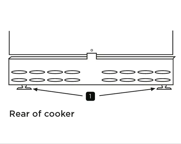
Adjusting Rear Wheels: Open the lower doors. Use a flat-headed screwdriver inserted through the circular holes in the lower front frame to adjust the rear wheel height.
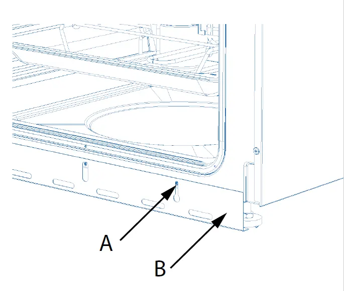
Fitting the Decorative Cover Plinth: If the feet are visible after levelling, attach the plinth by releasing the screws (A) slightly, aligning the keyway slots (B) with the screws, adjusting to the required height, and tightening by hand. Do not use power tools.
Fitting the Towel Rail: Applicable to 90cm, 100cm, and 110cm models. Align the towel rail holes with the fascia panel. Use the provided M6 screws and Allen key. Insert longer screws into the upper hole (A) and shorter screws into the lower hole (B). Tighten until flush, but do not over-tighten.
Dimensions and Clearances
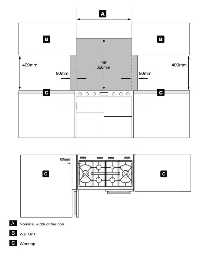
The area above and to either side of the hob must be kept clear of combustible materials. No shelf, overhang, or cooker hood may be lower than 650mm above the hob. If the appliance has a side-opening door and is placed next to a wall or side cabinets at a right angle, a side clearance of 60mm is recommended to allow the door to open fully. The cooker may be fitted flush to adjacent kitchen base units.
Electrical Connection
The appliance must be connected to a switch providing all-pole disconnection with a minimum contact separation of 3mm. Use a suitable flexible cable capable of withstanding a temperature rise of at least 70°C.
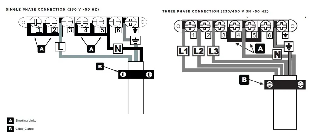
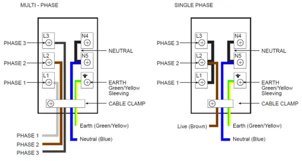
Single-Phase Connection: Place brass connecting bars between L1, L2, and L3. Connect the mains supply phase live wire to the L2 terminal. Leave neutral connecting bars in place.
Multi-Phase Connection: Remove the brass connecting bars from the live terminals. Connect the 3 phase cables to terminals L1, L2, and L3 respectively. Leave neutral connecting bars in place.
Always ensure the cable is routed clear of heat sources and that sufficient cable length is provided to allow the cooker to be pulled out without becoming twisted or trapped.
Commissioning
Check the operation of electrical components, including the clock programmer, minute minder, oven light, and convection fan. Set the time of day on the timer. If the cooker does not perform correctly, inform the customer, place a warning notice on the appliance, and if the fault is dangerous, disconnect it.
Technical Data
The appliance is a Class 1 freestanding cooker. Electrical supply is 230-400V ~3N ~ 50Hz. The total load is 18805W (Induction Unit 11040W). Standard oven light is 25W.
Manufacturer information
Stoves
Practical help
Common problems
Cooker is not level
Use a spirit level on a baking sheet on an oven shelf and adjust the levelling feet at the front and rear.
Electrical connection uncertainty
Ensure a competent person performs the connection. For single-phase, link L1+L2+L3 and connect live to L2. For multi-phase, remove links from L1, L2, and L3.
Oven door does not open fully
If the appliance is next to a wall or side cabinets, ensure a side clearance of 60mm.
Before use
- Remove all packaging and wrapping.
- Wash oven shelves, baking tray, air fry basket, and grill pan in hot soapy water.
- Turn ovens and grill on for a short while to burn off manufacturing residues.
- Ensure the appliance is earthed.
- Verify the appliance is connected by a competent person.
Specs in practice
- Electrical Supply
- 230-400V ~3N ~ 50Hz.
- Minimum Clearance
- 650mm above the hob for hoods or shelves.
- Levelling Height
- Adjustable for worktop heights between 900-930mm.
Images and diagrams
- Wiring diagrams for single and multi-phase connections are provided on page 11.
- Levelling feet adjustment is shown on page 6.
- Towel rail installation details are on page 7.
- Clearance requirements are illustrated on page 8.
Model compatibility
- Towel rail installation is applicable to 90cm, 100cm, and 110cm Richmond range cookers.

Manual page author
Michael Turner
Technical manual editor
Reviews PDF manuals for structure, safety notes, and practical product details so readers can find the right information quickly.