Home Appliances / Cookers & Ranges
Installation Guide for AGA ERA 110-3i Cooker
Professional installation guide for the AGA ERA 110-3i cooker. Includes critical safety warnings, electrical connection requirements, clearance specifications, and wiring diagrams for qualified installers.
Table of contents
Manual images
Click an image to enlargeQuick guide from the manual
This document provides essential installation requirements for the AGA ERA 110-3i cooker. Important: Installation must be performed by a qualified, factory-trained engineer. The unit is heavy (320kg) and requires specific electrical supply configurations, including a 32A supply for the cooker and a separate 13A supply for the induction hob.
Product Safety
Safety is paramount during installation. Ensure the following:
- The unit is heavy; use proper equipment and manpower to move it.
- The appliance must be permanently disconnected from the supply (Live and Neutral) before any electrical work.
- Do not store flammable vapors or liquids near the appliance.
- Ensure the appliance is properly earthed.
- Do not use steam cleaners on the cooker.
Installation Requirements
The AGA ERA arrives on a single pallet. Ensure there is adequate access to the kitchen to maneuver the unit, which has a footprint of approximately 1120mm x 735mm. The base or hearth must be level and capable of supporting the total weight of 320kg (705lbs).
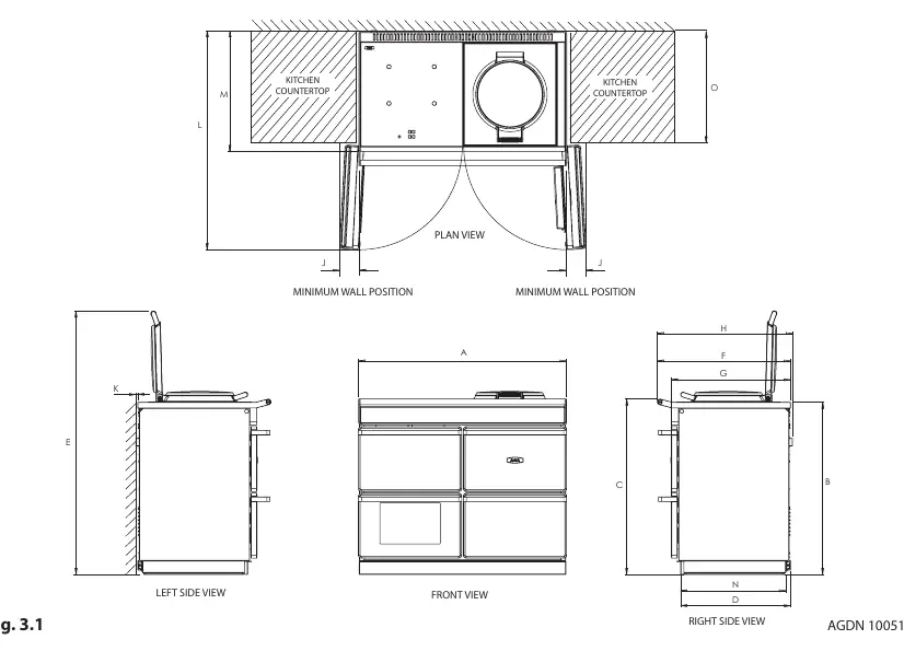
Clearances
Adhere to the following minimum clearance requirements for safe operation and servicing:
- Above: 60mm required above the raised insulating cover handle.
- Sides: 3mm gap between the cooker top plate and adjoining work surfaces.
- Side Walls: 130mm clearance required on both sides for oven door access.
- Front: 1000mm clearance required at the front for servicing.
- Rear: 10mm gap between the rear of the top plate and the wall.
If installing in a brick recess, increase minimum clearances by at least 10mm to account for non-square walls.
Power Supply
The cooker requires a 1PH 32A 230V or 240V 60Hz (or 40A 50Hz) fused electrical supply. The induction hob requires an additional, separate 240V 60Hz 13A power supply. The mains connection point must be accessible and the isolator must be fitted within 2 meters of the appliance.
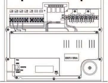
Wiring Diagram
The manual includes a detailed wiring diagram showing connections for the fan oven, roast oven elements, simmer oven element, and thermocouples. This diagram is intended for use by qualified service personnel only.
Contact Information
For further advice or information, contact your local AGA Specialist or Middleby Residential at 4960 Golden Pkwy, BLDG 3, Buford, GA 30518. Business Phone: 770.932.7282. Fax: 770.932.7292. Toll Free: 800.241.9152.
Practical help
Common problems
Cooker door clashing with kitchen cabinet handles
Ensure cabinet handles are at least 90mm away from the side of the cooker or ensure cabinet doors open away from the cooker.
Unit rocking or unstable
Use the provided shims to level the cooker on the base or hearth.
Electrical supply issues
Ensure a dedicated 32A supply for the cooker and a separate 13A supply for the induction hob are installed.
Before use
- Verify the floor/hearth can support 320kg (705lbs).
- Ensure a qualified, factory-trained engineer is performing the installation.
- Check that the 1000mm front clearance is available for future servicing.
- Confirm the electrical supply meets the 32A (cooker) and 13A (induction) requirements.
- Ensure the plinth cover is removable and not obstructed by flooring or tiles.
Specs in practice
- Appliance Weight
- 320kg (705lbs). Requires heavy-duty equipment for installation.
- Cooker Power Supply
- 1PH 32A 230V/240V 60Hz (or 40A 50Hz).
- Induction Hob Supply
- Separate 240V 60Hz 13A supply required.
- Side Clearance
- 130mm required if fitted against side walls for door access.
Images and diagrams
- Wiring diagram illustrates the main control board connections for elements and thermocouples.
- Cable routing diagram shows the required zones for the mains supply connection point.
Model compatibility
- Requires factory-trained engineer for installation.
- Optional adapter kit (Part No. AE4M280354) required for 2 or 3 phase installation.

Manual page author
Emily Carter
User documentation editor
Prepares concise manual descriptions and highlights the most useful setup, operation, and maintenance information for readers.