Home Appliances / Range Hoods
Installation Instructions for Stoves Richmond 100/110cm Electric Induction Cooker
Professional installation guide for Stoves Richmond 100/110cm Electric Induction Cooker. Includes detailed steps for levelling, electrical connection, door removal, and safety clearances.
Table of contents
Manual images
Click an image to enlargeImportant Installation Information
This document provides essential installation instructions for the Stoves Richmond 100/110cm Electric Induction Cooker. Installation must be performed by a competent person who is a member of a 'Competent Person Scheme' to ensure compliance with regulations. Failure to install the appliance correctly is dangerous and could lead to prosecution.
Safety and Warnings
- Earthing: This appliance must be earthed.
- Modifications: Do not modify this appliance.
- Ventilation: Ensure all specified vents, openings, and air spaces are not blocked. The space underneath and at the back of the appliance is critical for cooling.
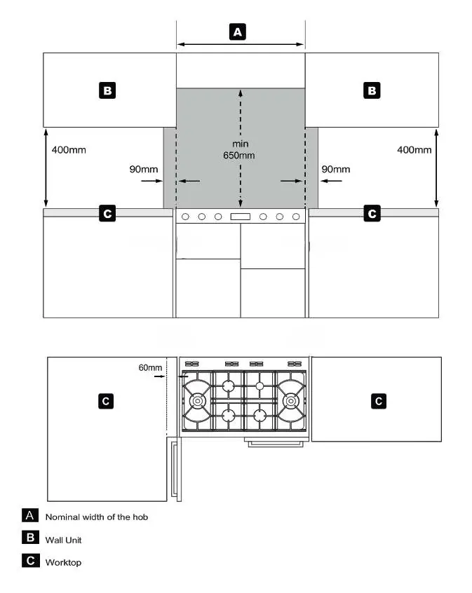
- Combustible Materials: No shelf, overhang, or cooker hood may be lower than 650mm above the hob.
- Handling: Panel edges may be sharp; use caution when moving the appliance. Do not lift by the door handles.
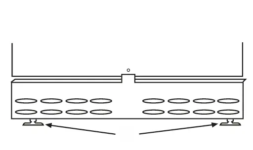
Levelling the Cooker
The cooker is fitted with levelling feet at the front. Place a spirit level on a baking sheet on an oven shelf to verify the level. The feet are supplied with two locknuts to adjust height between 900-930mm. For heights lower than 900mm, remove one locknut from each foot.
Adjusting Rear Wheels
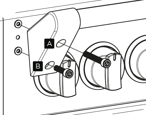
To adjust the height of the rear wheel assemblies:
- Open the lower oven doors.
- Insert a flat-headed screwdriver into the circular holes in the lower front frame.
- Turn the screwdriver to raise or lower the wheels.
- Note: On 100cm and 110cm models, you must remove the bottom-right slow cook compartment door to access the bottom-right circular hole.
Door Removal
To remove the slow cook compartment door for wheel adjustment or plinth fitting:
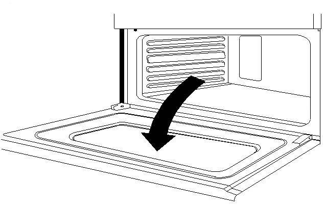
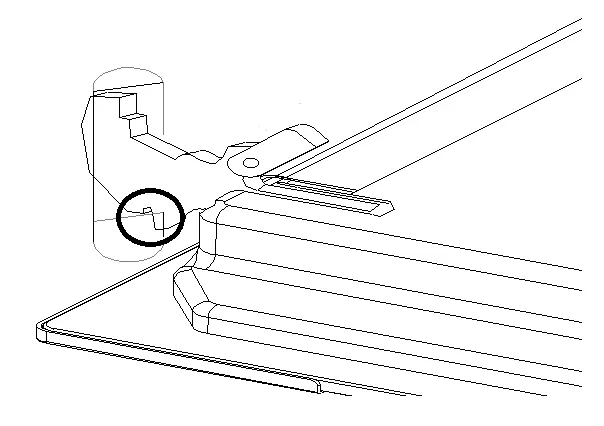
- Open the door fully.
- Pull the locking latch on each hinge forwards and downwards.
- Partially close the door to a 30-degree angle.
- Lift the door assembly up and out away from the cooker body.
Electrical Connection
The appliance must be connected to a switch providing all-pole disconnection with a minimum contact separation of 3mm. Use a suitable flexible cable capable of withstanding at least 70°C.
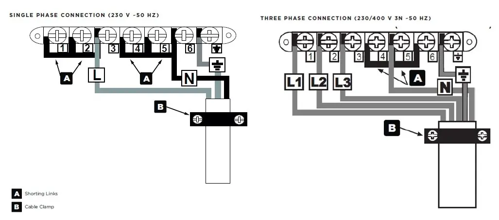
- Single-phase: Place brass connecting bars between L1 + L2 + L3. Link the mains supply phase live wire to the L2 terminal.
- Multi-phase: Remove brass connecting bars from live terminals. Connect the 3 phases to L1, L2, and L3 respectively.
- Neutral: Leave neutral connecting bars in place for all connection types.
Commissioning
Before handing over to the customer:
- Check the clock programmer/minute minder functions.
- Turn the main oven control knob to 'defrost' to verify the oven light and convection fan operate.
- Ensure the customer knows how to operate the clock and controls.
Manufacturer information
Stoves
Practical help
Common problems
Cooker is not level
Use the levelling feet at the front and adjust the rear wheels via the access holes in the lower front frame.
Stiff door hinges during removal
The locking latches may be stiff if never moved; use pliers if necessary to move them.
Electrical connection errors
Ensure shorting links are correctly configured for single-phase (L1+L2+L3) or removed for multi-phase installations.
Before use
- Remove all packaging and wrapping from inside the appliance.
- Wash oven shelves, baking tray, and grill pan in hot soapy water to remove protective oil.
- Verify the installation area is free of combustible materials.
- Ensure the electrical supply matches the technical data on the rating label.
- Confirm the appliance is properly earthed.
Specs in practice
- Electrical Supply
- 220-240V ~ 1N ~ 50 Hz or 380-415V ~ 3N ~ 50 Hz.
Images and diagrams
- Wiring diagrams for single-phase and three-phase electrical connections.
- Levelling feet adjustment procedure.
- Door removal sequence using hinge latches.
- Towel rail installation using M6 screws.
Model compatibility
- Applicable to Stoves Richmond 100cm and 110cm Electric Induction models.
- Installation must be performed by a competent person.

Manual page author
Michael Turner
Technical manual editor
Reviews PDF manuals for structure, safety notes, and practical product details so readers can find the right information quickly.