Lighting / Industrial Lighting
Installation Guide for Sunco Lighting LED Linear Highbay Light
A comprehensive installation guide for Sunco Lighting LED Linear Highbay Light. Includes step-by-step instructions for chain, surface, and pendant mounting, wiring diagrams, and safety precautions.
Quick answers from the manual
Quick answer
- This guide provides installation instructions for Sunco Lighting LED Linear Highbay Lights, covering chain, surface, and pendant mounting, wiring, and configuration. p. 1, 2
Key actions
- Chain Mounting p. 1
- Surface Mounting p. 2
- Pendant Mounting p. 2
Problems and fixes
Fixture not working
Check line voltage, grounding, and photocell functionality.
p. 2Show 2 more answers Show less
Technical specifications
| Parameter | Value | Meaning | Pages |
|---|---|---|---|
| Voltage | 120-347Vac | Input voltage | p. 2 |
Where to find it in the PDF
- Installation Instructions p. 1, 2
Table of contents
Manual images
Click an image to enlargeQuick Guide from the Manual
This document provides installation instructions for the Sunco Lighting LED Linear Highbay Light. It covers three mounting methods: chain, surface, and pendant. Always ensure the power is disconnected before starting any installation or maintenance work.
Safety Precautions
- Electrical Safety: Disconnect power before installation or servicing. Ensure the fixture is properly grounded and connected to a UL-listed junction box.
- Handling: Wear gloves and safety glasses. Do not touch the enclosure, lens, or light source while the fixture is on or hot.
- Environment: Keep combustible materials away from the lens. Do not restrict ventilation.
- Compatibility: Do not connect to dimmer packs, occupancy sensors, or timing devices unless specified.
Installation Methods
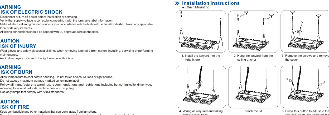
Chain Mounting
- Install the lanyard into the light fixture.
- Hang the lanyard from the ceiling anchor.
- Remove the screws and the cover.
- Perform wiring according to safety precautions.
- Lock the lid.
- Press the adjustment button to set the required length.
Surface Mounting (With Pendant Box or Kits)
- Drill holes according to the ceiling and size requirements.
- Mount the junction box to the ceiling or secure the surface mount kit.
- Install the light into the junction box or insert hook ends into the high bay light holes.
- Pass supply wires through the wiring cover and connect by color.
- Secure the wiring cover with screws.
Pendant Mounting
- Install the junction box on the 3/4" pipe.
- Install the light into the junction box and tighten the screws.
- Perform wiring and close the cover.
Wiring and Configuration
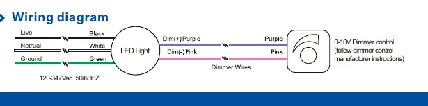
The fixture supports 120-347Vac 50/60Hz input. The wiring diagram indicates connections for Live, Neutral, Ground, and 0-10V Dimmer control (Purple/Pink wires). The fixture features selectable wattage and CCT (4000K/5000K) settings.
Troubleshooting
- If the fixture is not working, check that the line voltage is correct.
- Ensure the fixture is grounded properly.
- Verify that the photocell (if used) is functioning correctly.
Practical help
Common problems
Fixture fails to light up
Check that the line voltage is correct and the fixture is properly grounded.
Photocell not working
Ensure the photocell is installed correctly and functioning properly.
Before use
- Inspect the fixture for freight damage upon receipt.
- Verify supply voltage matches the fixture label.
- Ensure power is disconnected before installation.
- Wear gloves and safety glasses.
- Ensure the fixture is connected to a grounded UL-listed junction box.
Show more Show less
Specs in practice
- 120-347Vac 50/60Hz
- The input voltage range and frequency the fixture supports.
- Wattage Selectable
- Allows adjustment of power output between specific ranges.
- CCT Selectable
- Allows adjustment of color temperature between 4000K and 5000K.
Images and diagrams
- Wiring diagram shows connections for Live, Neutral, Ground, and 0-10V Dimmer control wires (Purple/Pink).
Model compatibility
- Do not connect to dimmer packs, occupancy sensors, or timing devices unless specified.
- Must be connected to a properly installed and grounded UL-listed junction box.

Manual page author
Emily Carter
User documentation editor