Tools / Generators
FNIRSI-1014D Digital Oscilloscope and Signal Generator
Comprehensive user manual for the FNIRSI-1014D, a 2-in-1 desktop digital oscilloscope and signal generator featuring a 7-inch display, 1GSa/s sampling rate, and 100MHz bandwidth.
Table of contents
Manual images
Jump to the sectionProduct Overview
The FNIRSI-1014D is a versatile 2-in-1 device combining a high-performance digital storage oscilloscope with a built-in DDS signal generator. Designed for maintenance, research, and development, it features two channels with a 1GSa/s real-time sampling rate and 100MHz analog bandwidth. The device is equipped with a 7-inch 800x480 high-resolution LCD screen, providing clear visualization of waveforms.
Key Features
- Triggering: Comprehensive trigger functions (single, normal, auto) suitable for both periodic analog and aperiodic digital signals.
- Signal Generator: Built-in DDS generator with 14 standard waveforms and customizable chopping output, capable of storing up to 1000 custom signals.
- High-Voltage Protection: Integrated module withstands up to 400V DC, protecting the device even if the probe is not set to 10x.
- Storage and Connectivity: 1GB internal storage for up to 1000 screenshots and 1000 waveform data groups. Includes USB interface for computer connectivity and screen sharing.
- Advanced Analysis: Features include cursor measurement, FFT display for harmonic analysis, and Lissajous graphic display for phase and frequency comparison.
Safety and Operation
Important Safety Warning: When using two channels simultaneously, the ground terminals of both probes must be connected together. Connecting them to different potentials, especially high-power equipment or 220V mains, will cause a short circuit and damage the motherboard. Always use the original power supply to avoid ground loops.
Probe Usage: The 1x probe has a 5MHz bandwidth, while the 10x probe supports up to 100MHz. For frequencies above 5MHz, ensure both the probe switch and the oscilloscope settings are set to 10x to prevent signal attenuation due to cable capacitance.
Maintenance and Troubleshooting
The device includes an automatic calibration feature for the horizontal baseline. If the baseline does not align with the 0V indicator, remove the probe and run the baseline calibration from the menu. For common issues like no waveform display, ensure the trigger mode is set to auto and the probe is properly connected. If the device fails to power on, verify the power source and try a different charging adapter.
Practical help
Common problems
Device does not turn on
Check power cord connection and power outlet. Try replacing the charging adapter.
Only a flat line on screen
Check if 'pause' is active, press [auto], or verify probe connection and signal source.
Voltage or frequency reads 0
Adjust vertical sensitivity and time base, or press [auto] to ensure a clear periodic waveform is displayed.
Waveform shakes and cannot be fixed
Adjust the trigger voltage so the green arrow is within the waveform range, or enable 'auto 50%' in the menu.
Significant attenuation above 5MHz
Switch both the probe and the oscilloscope input setting to 10x.
Before use
- Ensure the original power supply is used.
- Verify probe switch matches the oscilloscope input setting (1x/10x/100x).
- Connect ground clips of both probes together if using two channels.
- Perform baseline calibration if the 0V indicator does not align with the baseline.
- Ensure the signal source is active and properly connected.
Specs in practice
- Sampling Rate
- 1GSa/s real-time sampling for high-precision waveform capture.
- Input Voltage
- Maximum 400V peak-to-peak tolerance on BNC input.
Images and diagrams
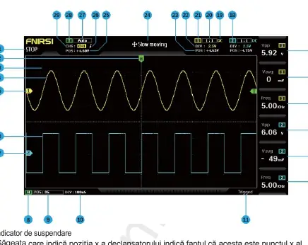
- 1-7: Waveform data and baseline indicators for channels 1 and 2.
- 8-10: Horizontal time base controls and indicators.
- 11: Trigger status indicator.
- 12-17: Measurement parameter columns (F1-F6).
- 18-29: Channel control, coupling, and trigger settings.
Model compatibility
- Only use 100MHz or higher bandwidth probes for full performance.
- 100x or 1000x probes are required for high-voltage/high-frequency measurements (e.g., induction cookers, transformers).
- USB interface allows for computer connectivity and screen sharing.

Manual page author
Emily Carter
User documentation editor
Prepares concise manual descriptions and highlights the most useful setup, operation, and maintenance information for readers.