HVAC / Ventilation Systems
Product Card for Systemair RVK 200E2-L SILEO Circular Duct Fan
Quick guide for the Systemair RVK 200E2-L SILEO circular duct fan. Includes technical specifications, wiring diagrams, installation dimensions, and product features.
Quick answers from the manual
Quick answer
- The Systemair RVK 200E2-L SILEO is a speed-controllable circular duct fan designed for installation in ducts. It features an IP44-rated terminal box, integrated thermal contacts, and can be installed in any position. p. 1
Key actions
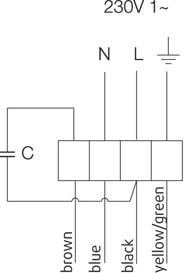
- Connect the fan to a 230V 1~ power supply according to the wiring diagram. p. 5
Problems and fixes
Motor overheating
The unit has integrated thermal contacts with manual reset.
p. 1Show 3 more answers Show less
Maintenance and reset
- The motor has integrated thermal contacts with manual reset. p. 1
Technical specifications
| Parameter | Value | Meaning | Pages |
|---|---|---|---|
| Voltage | 230 V | Operating voltage | p. 1 |
| Frequency | 50 Hz | Operating frequency | p. 1 |
| Weight | 3.9 kg | Unit weight | p. 1 |
Where to find it in the PDF
- Technical Data p. 1
- Wiring Diagram p. 5
- Dimensions p. 4
Table of contents
Manual images
Click an image to enlargeQuick guide from the manual
This document serves as a product card for the Systemair RVK 200E2-L SILEO circular duct fan. It provides essential technical data, installation dimensions, and wiring information. The fan is designed for duct installation and features speed-controllable operation, integrated thermal contacts, and an IP44-rated terminal box, making it suitable for wet room applications.
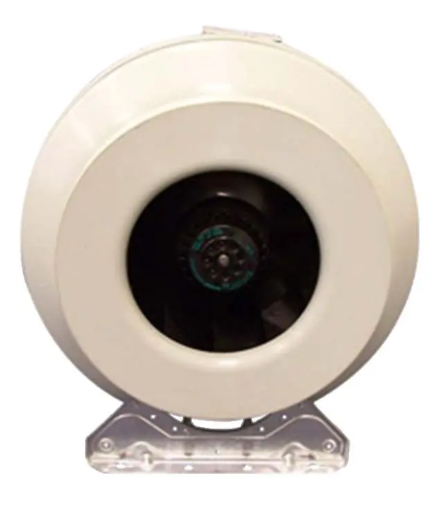
Product Description
The RVK sileo series is designed for installation in ducts. The casing is manufactured from PP fibreglass reinforced plastic, providing a low-leakage design. The fans feature high-efficiency backward-curved blades and external rotor motors. Key features include:
- Speed-controllable via stepless thyristor or 5-step transformer.
- Integrated thermal contacts with manual reset to protect against overheating.
- Suitable for installation in any position.
- Maintenance-free and reliable operation.
- IP44-rated terminal box.
Technical Specifications
The following nominal data applies to the RVK 200E2-L SILEO model:
- Voltage: 230 V
- Frequency: 50 Hz
- Phase: 1 ~
- Input Power (P1): 153 W
- Current: 0.672 A
- Max. Airflow: 0.28 m³/s
- R.p.m.: 2533 r.p.m.
- Capacitor: 4 µF
- Weight: 3.9 kg
- Max. Temperature (Transported Air): 70 °C (55 °C when speed-controlled)
- Sound Pressure Level (at 3m): 44.9 dB(A)
Installation and Wiring
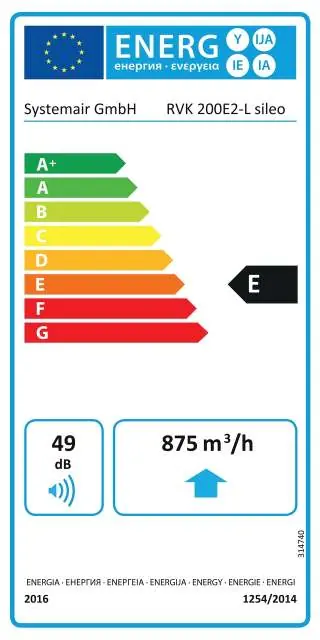
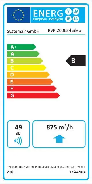
The fan is designed for easy installation in ducts. The included mounting bracket facilitates installation and removal while preventing vibration transfer. Refer to the wiring diagram provided in the documentation for electrical connections, ensuring the unit is connected to a 230V 1~ power supply. The terminal box is IP44 rated.
Dimensions
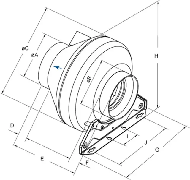
The unit dimensions are provided in the technical documentation. Ensure sufficient space is allocated for the fan housing and duct connections based on the specified diameter (DN 200).
Practical help
Common problems
Motor overheating
The unit has integrated thermal contacts with manual reset. Ensure proper ventilation and check for obstructions in the ducting.
Speed control issues
The fan is compatible with stepless thyristors or 5-step transformers. Ensure the controller is compatible with the motor specifications.
Before use
- Verify the power supply is 230V, 50Hz.
- Ensure the ducting is compatible with the 200mm diameter.
- Check for proper electrical connection according to the wiring diagram.
- Confirm the mounting position is secure (can be installed in any position).
- Ensure the terminal box is properly sealed.
Show more Show less
Specs in practice
- Thermal contacts
- Safety feature to prevent motor overheating with manual reset.
Images and diagrams
- Wiring diagram shows connections for N, L, and Ground (yellow/green).
- Dimensions diagram provides measurements for A, B, C, D, E, F, G, H, I, J.
Model compatibility
- Compatible with stepless thyristor or 5-step transformer speed controllers.
- Suitable for wet room applications due to air-tight casing and IP44 terminal box.

Manual page author
Emily Carter
User documentation editor