HVAC / Ventilation Systems
User Manual for Systemair SAVE VTR 200/B Ventilation Unit
Comprehensive user guide for the Systemair SAVE VTR 200/B ventilation unit. Includes operation instructions, control panel settings, maintenance procedures (filter replacement, cleaning), and troubleshooting alarms.
PDF source: NO · summary: English
Quick answers from the manual
Quick answer
- The Systemair SAVE VTR 200/B is a ventilation unit with heat recovery. It is operated via a control panel to adjust temperature, airflow, and weekly schedules. Maintenance includes regular filter changes, cleaning the heat exchanger and fans, and replacing the rotor belt. p. 4
Key actions
- Change filters every 12 months and reset the timer. p. 7, 8
- Clean heat exchanger every 3 years. p. 9
First start
- Plug the unit into the power outlet and verify it starts. p. 4
Show 4 more answers Show less
Problems and fixes
Rotor alarm
Check rotor belt or sensor gap (5-10mm).
p. 14
EMT/Frost alarm
Check frost guard or overheating protection.
p. 14Maintenance and reset
- Reset filter timer in the service menu. p. 8
Technical specifications
| Parameter | Value | Meaning | Pages |
|---|---|---|---|
| Heater power | 500 W or 1000 W | Electric post-heater capacity. | p. 4 |
Where to find it in the PDF
- Control Panel p. 4
- Maintenance p. 6, 7, 8, 9
- Troubleshooting p. 14, 15
Table of contents
Manual images
Click an image to enlargeQuick guide from the manual
The Systemair SAVE VTR 200/B is a ventilation unit with heat recovery designed for smaller homes. It is operated via a control panel to adjust temperature, airflow, and weekly schedules. Regular maintenance, including filter changes and cleaning, is essential for optimal performance.
Control panel
The control panel is used to make adjustments to the system. It features a display, a selection wheel (VALG-hjul), an ENTER button, and a RETURN button.
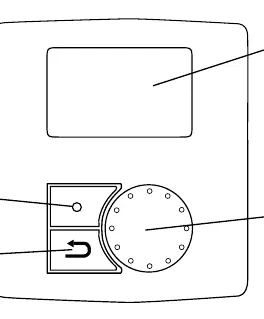
- Display: Shows symbols, menus, and settings.
- VALG-hjul: Rotate to browse menus or change settings.
- ENTER: Confirm menu selections or settings.
- RETURN: Go back to the previous level or cancel a parameter change.
Settings
Temperature
The supply air temperature can be adjusted in 1 K increments. If an electric heater is installed, the range is 12-22 °C. With a water heater, the range is 12-40 °C. If heaters are deactivated, the range is 15-19 °C.
Airflow
Airflow can be set to five levels: Off, Low, Normal, High, and Auto. Note that manual fan stop should not be used in residential settings unless the unit is equipped with dampers to prevent cold drafts and condensation.
Maintenance
Maintenance should normally be performed 3-4 times a year.
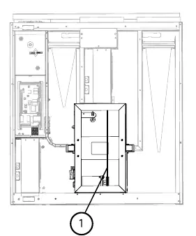
Filter replacement
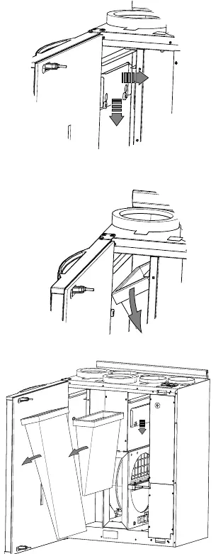
Filters should be changed every 6, 9, 12, or 15 months (standard is 12 months). After changing, the filter timer must be reset in the service menu.
- Loosen screws to remove filter locks.
- Tilt the filter and pull it out.
- Insert new filter and secure locks.
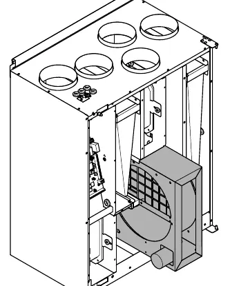
Heat exchanger cleaning
Clean the heat exchanger at least every 3 years or as needed.
- Disconnect power to the rotor and rotor sensor.
- Pull the rotor out.
- Wash in warm soapy water (do not use ammonia-based detergents).
- Rinse and allow to dry before reinstalling.
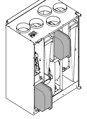
Fan cleaning
Fan blades may accumulate dust over time. Disconnect power, pull the fans out, and clean with a cloth or soft brush. Do not use water; white spirit may be used for stubborn deposits.
Troubleshooting
Alarms are indicated by a warning triangle on the display. Common alarms include:
- Vifte: Fault in supply or extract fan. Check quick-connectors.
- EMT/Frost: Triggered frost guard or overheating protection.
- Rot: Rotor fault. Check rotor belt and sensor gap (5-10 mm).
- Filter: Time to change filter.
Practical help
Common problems
Rotor alarm
Check the rotor belt for damage or breakage. Ensure the sensor gap is 5-10 mm from the magnet.
Low supply air temperature
Check if the overheating protection has been triggered. Press the reset button on the unit.
Filter alarm
Replace the filters and reset the filter timer in the service menu.
Before use
- Ensure the unit is connected to the power supply.
- Verify that filters are installed correctly.
- Check that ventilation ducts are clear and not blocked.
- Ensure the front hatch is properly closed.
Show more Show less
Images and diagrams
- Control panel layout showing display, wheel, and buttons.
- Filter removal procedure showing screw and lock locations.
- Rotor belt replacement steps.
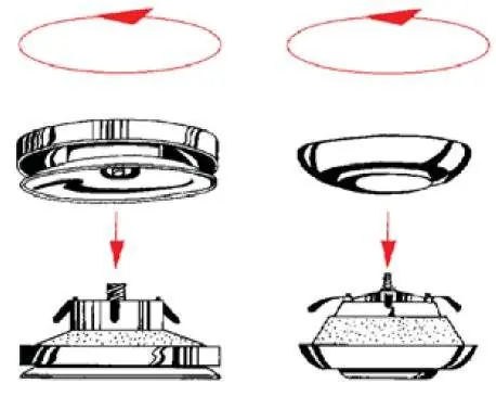
- Ventilation valve cleaning and maintenance.
Model compatibility
- Available as left and right models.
- Supports electric or water heater options.

Manual page author
Emily Carter
User documentation editor