Lighting / Controllers & Dimmers
User Manual for T-LED 1KRF Single Color LED Controller
Quick guide for the T-LED 1KRF Single Color LED Controller. Includes wiring diagrams, remote pairing instructions, Push-Dim setup, and troubleshooting steps.
Quick answers from the manual
Quick answer
- The T-LED 1KRF is a single-channel LED controller for 5-36VDC systems. It supports RF 2.4G remote control and Push-Dim functionality for dimming. p. 1
Key actions
- Pairing a remote using the Match Key p. 1
- Using Push-Dim for dimming p. 2
First start
- Connect the power supply (5-36VDC) to the input terminals and the LED strip to the output terminals. p. 2
Problems and fixes
No light
Check power and connections.
p. 2Maintenance and reset
- Restore factory default parameters by long pressing the match key for 10s. p. 2
Technical specifications
| Parameter | Value | Meaning | Pages |
|---|---|---|---|
| Input Voltage | 5-36VDC | Operating voltage range | p. 1 |
| Output Current | 8A | Maximum output current | p. 1 |
Where to find it in the PDF
- Technical Parameters and Pairing p. 1
- Wiring and Troubleshooting p. 2
Table of contents
Manual images
Click an image to enlargeQuick guide from the manual
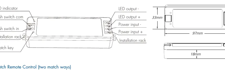
The T-LED 1KRF is a single-color LED controller designed for 5-36VDC constant voltage applications. It supports RF 2.4G remote control, auto-transmitting, and Push-Dim functionality. Key features include 4096 levels of smooth dimming, over-heat/over-load protection, and the ability to synchronize multiple controllers.
Installation and Wiring
Proper installation is critical for performance and safety. Ensure the power supply output is at least 1.2 times the load power to prevent flickering.
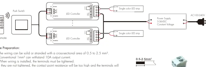
- Wire Preparation: Use solid or stranded wire with a cross-sectional area of 0.5 to 2.5 mm².
- Terminals: Ensure all terminals are tightened securely to prevent high contact resistance and overheating.
- Spacing: Maintain a distance of at least 20cm between products to ensure proper heat dissipation.
- Interference: Do not install close to switching power supplies or metal objects (keep at least 20cm distance).
- Height: Install at least 1m from the floor to ensure optimal remote control signal reception.
Operation and Remote Pairing
The controller can be paired with RF 2.4G remotes using two methods:
- Using Match Key: Short press the match key on the controller, then immediately press the on/off key (single zone) or zone key (multiple zone) on the remote. The LED indicator will flash to confirm success.
- Using Power Restart: Switch off the power to the receiver, then switch it back on. Immediately short press the on/off key (single zone) or zone key (multiple zone) on the remote 3 times. The light will blink 3 times to confirm success.
- Deleting Matches: Use the match key (press and hold for 5s) or the power restart method (switch off/on, then press the remote key 5 times).
Push-Dim Function
The Push-Dim interface allows control via a standard non-latching wall switch:
- Short press: Turn light on or off.
- Long press (1-6s): Step-less dimming. Every other long press reverses the dimming direction.
- Synchronization: If multiple controllers are connected to the same push switch, long press for more than 10s to synchronize all lights to 100% brightness.
Troubleshooting
If you encounter issues, check the following:
- No light: Check power supply and connections.
- Uneven intensity: Often caused by long output cables or thin wire diameter. Reduce cable length or use thicker wire.
- No response from remote: Replace battery, reduce distance, or re-match the remote.
Practical help
Common problems
No light
Check the power supply and ensure all connections are secure.
Uneven intensity between front and rear
Reduce the length of the output cable, use a larger wire diameter, or add a power repeater.
No response from remote
Replace the remote battery, reduce the distance to the controller, or re-pair the remote.
Before use
- Verify input voltage is between 5-36VDC.
- Ensure wire cross-section is between 0.5 and 2.5 mm².
- Tighten all terminal screws securely.
- Ensure power supply capacity is at least 1.2x the load.
- Maintain 20cm clearance from other devices and metal objects.
Specs in practice
- Input Voltage
- 5-36VDC constant voltage required.
- Output Current
- 1 channel, 8A maximum.
- Control Distance
- 30m in barrier-free space.
Images and diagrams
- The wiring diagram illustrates the connection between the AC power supply, the LED controller, and the LED strip.
- It shows the specific terminals for Power Input (+/-) and LED Output (+/-).
Model compatibility
- Compatible with RF 2.4G single or multiple zone remotes.
- Supports connection to external non-latching push switches.

Manual page author
Michael Turner
Technical manual editor
Reviews PDF manuals for structure, safety notes, and practical product details so readers can find the right information quickly.