Lighting / LED Strips
User Manual for AVSL 153.743UK RGB/RGBW Sound Active Controller
Quick guide for the AVSL 153.743UK RGB/RGBW Sound Active Controller. Learn how to wire, pair the remote, set up sound-activated modes, and configure custom colors.
Table of contents
Manual images
Click an image to enlargeQuick Start Guide
This controller is designed for RGB/RGBW LED tape. To get started, ensure your power supply matches the voltage of your LED tape (12V or 24V). Connect the tape to the controller terminals, remove the battery tab from the remote, and power on the unit. Use the SET button to configure the controller for your specific tape type (slow flash for RGB, fast flash for RGBW).
Device Overview
The AVSL 153.743UK is a wireless controller for multi-colour LED tape. It features an internal microphone for sound-activated effects and a 3.5mm audio input for line-level sources. The unit supports common anode wiring and provides up to 5A per channel for RGB or 4A per channel for RGBW.
Installation and Wiring
Proper wiring is essential for safe operation. Ensure the power supply and controller have sufficient current capacity for the connected LED tape.
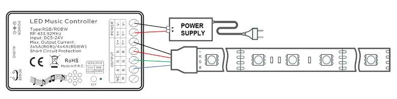
- Power Input: Connect 12Vdc or 24Vdc power to the DC5521 jack or the power input terminals.
- LED Output: Connect the +V, R, G, B (and W for RGBW) wires to the corresponding screw terminals on the controller.
- Audio Input: Use the 3.5mm jack for external audio sources if not using the internal microphone.
- Sensitivity: Adjust the rotary sensitivity control to tune the sound-activated triggering.
Remote Control Operation
The included 24-key RF remote allows for full control over the lighting effects:
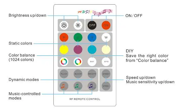
- Static Colours: Select from 8 preset colours.
- Dynamic Modes: Use FLASH, BLOOM, or SMOOTH keys to trigger auto sequences. Speed can be adjusted with SPEED+/SPEED- keys.
- Sound Modes: F.T. (flash effect), M.T. (morph effect), and C.T. (scroll effect).
- Colour Balance: Use the colour balance keys to manually set one of 1024 colours.
- DIY Keys: Long press (3 seconds) to save a custom colour setting. Short press to activate the saved setting.
Pairing and Clearing
Each controller is uniquely coded to its remote. If you need to pair or re-pair:
Pairing Method 1
- Press and hold the FLASH key.
- Power on the controller; LEDs will turn 50% white.
- Press the FLASH key 3 times within 3 seconds.
Pairing Method 2
- Power on the controller.
- Press and hold the SET button on the receiver for 5 seconds until the indicator lights up.
- Hold SET on the controller and press FLASH on the remote once.
To clear pairing, follow the same steps as above but use the SMOOTH key instead of the FLASH key.
Safety Warnings
- Never immerse the device in water or expose it to damp conditions.
- Do not use the device if it appears damaged.
- Do not attempt to repair or disassemble the unit, as this will invalidate the warranty.
Practical help
Common problems
LEDs are not lit after installation
Ensure the power supply is connected and active. Press the 'ON' key on the remote. Check that the battery tab has been removed from the remote.
Controller not responding to remote
Check the CR2025 battery in the remote. Ensure you are within the 20m range. If necessary, re-pair the remote using the pairing methods described.
Incorrect colours or modes
Use the 'SET' button to ensure the controller is set to the correct tape type (slow flash for RGB, fast flash for RGBW).
Before use
- Remove the plastic battery tab from the remote control.
- Verify that your power supply voltage (12V or 24V) matches your LED tape.
- Ensure the power supply has sufficient current capacity for the total length of LED tape.
- Check that all wires (+V, R, G, B, W) are securely connected to the correct terminals.
- Confirm the LED tape is of the common anode type.
Specs in practice
- Input Voltage
- DC 5V-24V; must match the voltage rating of your LED tape.
- Max Output Current
- 3x5A for RGB (15A total) or 4x4A for RGBW (16A total).
- RF Frequency
- 433.92MHz; the frequency used for remote control communication.
Images and diagrams
- The wiring diagrams illustrate the connection of the power supply to the 'POWER' terminals and the LED tape to the 'OUTPUT' terminals.
- The remote layout diagram identifies the specific buttons for static colours, dynamic modes, sound-activated modes, and DIY colour saving.
Model compatibility
- Compatible with 12V or 24V RGB/RGBW LED tape.
- Requires common anode LED tape.
- For long runs exceeding current limits, use RGB/RGBW amplifiers.

Manual page author
Emily Carter
User documentation editor
Prepares concise manual descriptions and highlights the most useful setup, operation, and maintenance information for readers.