Automotive / Car Audio
User Manual for Taramps BASS 15K Amplifier
Quick guide for the Taramps BASS 15K amplifier. Includes installation instructions, wiring diagrams, safety precautions, LED indicator explanations, and technical specifications.
Table of contents
Manual images
Click an image to enlargeQuick guide from the manual
The Taramps BASS 15K is a high-performance car audio amplifier. This document provides essential instructions for safe installation and operation. Key requirements include installation by a qualified professional, the use of 12V batteries, and the installation of a 650A fuse or circuit breaker as close to the battery as possible. Ensure the amplifier is installed in a firm, dry, and well-ventilated location with at least 1 inch (25mm) of space around the heatsink to prevent thermal shutdown.
Functions, inputs & outputs
The amplifier features several controls to fine-tune your audio experience:
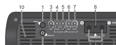
- INPUT: RCA input for signal from CD/DVD player. Use shielded cables to avoid noise.
- THRU OUT: Sends the input signal to another amplifier.
- LEVEL: Adjusts input sensitivity to match the signal levels of your audio source.
- SUBSONIC: Variable adjustment (8Hz to 30Hz) to set the start of the operating frequency.
- LOW PASS (LPF): Variable adjustment (60Hz to 250Hz) to set the end of the operating frequency.
- FREQ: Sets the center frequency for the Bass Boost (35Hz to 60Hz).
- BASS BOOST: Variable reinforcement for sub-bass (0 to +12dB).
- REMOTE TERMINAL: Connects to the remote output of the head unit using a 0.75mm² cable.
- SPEAKER: Output terminals for loudspeakers. Observe polarity and minimum impedance.
Power supply connector
Proper power connection is critical for performance and safety:

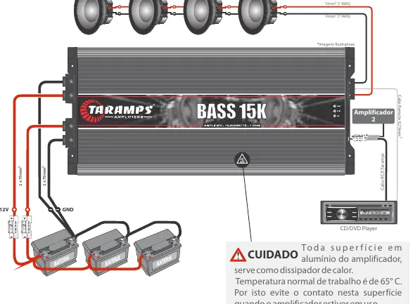
- Negative Terminal: Use a 2 x 70mm² (2/0 AWG) cable, kept as short as possible, connected to the negative battery pole.
- Positive Terminal: Use a 2 x 70mm² (2/0 AWG) cable directly from the positive battery terminal.
- Fuse/Breaker: A 650A fuse or circuit breaker is mandatory and must be installed as close to the battery as possible.
Caution: Always disconnect the negative battery terminal before making any connections to the amplifier.
LEDs indicators & protection system
The amplifier includes diagnostic LEDs to indicate status:
- ON (Blue): Indicates the amplifier is powered on.
- CLIP (Yellow): Indicates the amplifier is operating at the threshold of distortion or excessive temperature.
- PROT (Red): Indicates a fault. If flashing, check for short circuits, low impedance, or supply voltage issues (below 9V or above 17V).
The amplifier features thermal protection; if the internal temperature gets too high, the audio will be interrupted, and the yellow LED will flash until the unit cools down.
Installation
The amplifier must be installed in a location with adequate airflow. Do not embed the amplifier, as this will obstruct the internal cooling fans and lead to thermal protection activation. Ensure all cables have tinned ends for better electrical contact.
Technical specifications
The BASS 15K is designed for 1 Ohm minimum output impedance. It delivers 15000W RMS at 1 Ohm and 8505W RMS at 2 Ohms (at 14.4VDC). The frequency response ranges from 8Hz to 250Hz.
Practical help
Common problems
LED PROT flashing 2x
Supply voltage is below 9V. Check battery and power connections.
LED PROT flashing 3x
Supply voltage is above 17V. Check charging system.
LED CLIP flashing
Amplifier is operating at the threshold of distortion or excessive temperature. Reduce gain or improve ventilation.
Thermal protection active
Internal temperature is too high. The amplifier will automatically resume once cooled. Ensure fans are not obstructed.
Before use
- Installation must be performed by a qualified professional.
- Use 12V batteries.
- Install a 650A fuse or circuit breaker near the battery.
- Ensure at least 1 inch (25mm) of space around the heatsink.
- Disconnect the negative battery terminal before making connections.
- Use 2 x 70mm² (2/0 AWG) cables for power supply.
Specs in practice
- Input Sensitivity
- 280mV.
- Frequency Response
- 8Hz to 250Hz (-3dB).
Images and diagrams
- The wiring diagram illustrates the connection of the amplifier to the battery bank, including the mandatory circuit breakers and the remote turn-on wire.
- The control panel diagram identifies the location of input, level, crossover, and bass boost adjustments.
Model compatibility
- Minimum output impedance: 1 Ohm.
- Requires 2 x 70mm² (2/0 AWG) power cables.
- Requires 0.75mm² (18 AWG) remote cable.

Manual page author
Michael Turner
Technical manual editor
Reviews PDF manuals for structure, safety notes, and practical product details so readers can find the right information quickly.