Automotive / Car Audio
User Manual for Hertz MP 15K UNLIMITED Amplifier
Quick guide for the Hertz MP 15K UNLIMITED car amplifier. Learn about installation, wiring, output modes, Master/Slave configuration, and technical specifications.
Table of contents
Manual images
Click an image to enlargeQuick guide from the manual
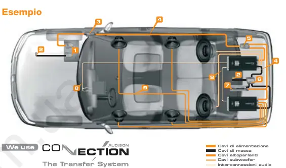
The Hertz MP 15K UNLIMITED is a high-power car audio amplifier designed for SPL competitions. It features a unique Direct Current connection system for low-resistance power transfer and supports the Hertz SPL Stack System for cascading multiple units. This manual provides essential instructions for installation, configuration, and maintenance.
Safety Precautions
- Ensure the vehicle electrical system is 12V DC with negative ground.
- Always wear protective eyewear when using tools.
- Install the amplifier in a well-ventilated area, away from moisture and heat sources.
- Use high-quality cables and connectors.
- Install a fuse holder within 40 cm of the battery positive terminal. The fuse value must be 50% higher than the amplifier's internal fuse.
- Do not install the amplifier inside the engine compartment.
Input/Control/Power Output Panel
The amplifier features various controls for fine-tuning:
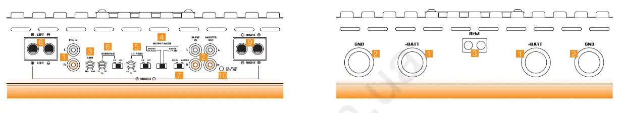
- PRE IN: Right and Left pre-amplified inputs.
- GAIN: Adjusts input sensitivity.
- OUTPUT MODE: Selects between STEREO BY-PASS, BRIDGE, or L+R MIX.
- LO-PASS / SUBSONIC: Filters available in BRIDGE/L+R MIX modes.
- MASTER / SLAVE: Switch for cascading multiple amplifiers.
Output Modes
The amplifier supports three main output configurations:
- STEREO BY-PASS: Standard stereo operation. Crossover filters are bypassed.
- L+R MIX: Sums inputs to mono. Requires specific polarity wiring for the Right output to maintain phase.
- BRIDGE: Mono operation for maximum power.
MASTER / SLAVE Mode
This mode allows you to cascade multiple MP 15K UNLIMITED amplifiers:
- Set the amplifier receiving the head unit signal as MASTER.
- Set the second amplifier as SLAVE.
- Connect MASTER OUT (L/R) to SLAVE IN (L/R) using an RCA cable (max 50 cm).
- Only the MASTER amplifier controls will manage the signal.
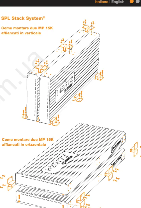
Installation and SPL Stack System
The amplifier can be mounted individually or stacked using the provided SPL Stack System brackets. Ensure the amplifier is securely fixed to the vehicle structure. When stacking, use the supplied 2 mm thick iron brackets to connect units vertically or horizontally.
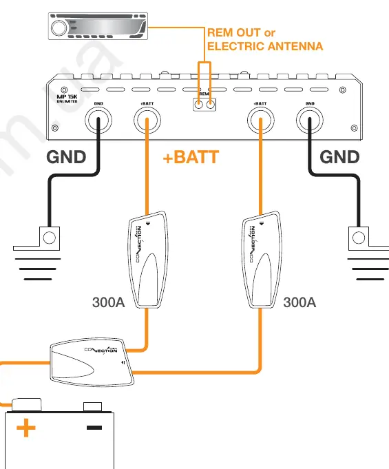
Power Supply Connection
Use 1/0 AWG cables for power. Connect both +BATT terminals directly to the battery positive terminal through fuse holders. Connect GND terminals directly to the battery negative terminal for best performance.
LED Status Indicators
- Green LED: Amplifier is on and working correctly.
- Red LED: Amplifier is in protection mode (short circuit, overheating, DC offset, or polarity reversal).
Technical Specifications
- Voltage: 8-18 VDC
- Power Output (14.4V, 1% THD): Up to 12,000W RMS (Bridge mode @ 1 Ohm)
- Input Sensitivity: 0.3 - 7V
- Damping Factor: > 950 (100 Hz @ 4 Ohm)
Manufacturer information
Hertz
Practical help
Common problems
LED is red
Indicates protection mode. Check for short circuits in speaker cables, overheating (>80°C), DC current in output, or reversed power polarity.
Amplifier overheating
Ensure adequate air circulation around the heat sink fins. Do not obstruct the cooling system. Check environmental temperature.
No sound
Check the remote turn-on cable voltage (must be 7-18V). Verify all power and speaker connections.
Before use
- Verify vehicle electrical system is 12V DC with negative ground.
- Use 1/0 AWG cables for power and ground.
- Install a fuse holder within 40cm of the battery positive terminal.
- Ensure minimum load is 1 Ohm.
- Check alternator and battery condition to handle increased load.
Specs in practice
- Power Output
- Up to 15,500W RMS @ 18V DC in Bridge mode.
- Input Sensitivity
- Adjustable range from 0.3V to 7V to match source output.
- Damping Factor
- > 950 (100 Hz @ 4 Ohm) indicates excellent control over speaker movement.
Images and diagrams
- Wiring Diagram: Shows battery, fuse holders, remote turn-on, and amplifier connections.
- Master/Slave: Illustrates cascading two amplifiers using RCA cables.
Model compatibility
- Minimum load: 1 Ohm.
- Voltage range: 8-18V DC.
- Requires 1/0 AWG power cables.

Manual page author
David Miller
Documentation analyst
Organizes user manual content into clear summaries, with attention to model details, product context, and everyday usability.