Sports / Fitness
Assembly and Operating Instructions for Taurus Elite 2-Tier Dumbbell Rack
Comprehensive assembly and operating guide for the Taurus Elite 2-Tier Dumbbell Rack (TF-PTT0265). Includes setup instructions, safety guidelines, maintenance tips, and technical specifications.
Quick answers from the manual
Quick answer
- The Taurus Elite 2-Tier Dumbbell Rack (TF-PTT0265) is a professional-grade storage solution. It requires assembly by at least two adults and supports a maximum load of 380 kg per level (760 kg total). p. 1, 8, 11
Key actions
- Assemble the rack by attaching the placing frames to the floor standers using the provided screws and washers. p. 13
First start
- Assemble the unit on a flat, solid surface. Ensure at least two adults perform the assembly. Loosely screw parts together first, then tighten all screws. p. 11, 12, 13
Problems and fixes
Squeaking & cracking noises
Check or lubricate screw connections.
p. 15
Unit wobbles
Align unit or tighten screw connections.
p. 15Maintenance and reset
- Clean with a damp towel after each session. Inspect screw connections monthly. p. 16
Technical specifications
| Parameter | Value | Meaning | Pages |
|---|---|---|---|
| Max load | 760 kg | Total weight capacity | p. 8 |
| Dimensions | 228 x 65 x 80 cm | Set-up dimensions | p. 8 |
Where to find it in the PDF
- Assembly Instructions p. 11, 12, 13
- Technical Data p. 8
- Troubleshooting p. 15
Table of contents
Manual images
Click an image to enlargeQuick Guide
The Taurus Elite 2-Tier Dumbbell Rack (TF-PTT0265) is a professional-grade storage solution designed for home, semi-professional, and commercial use. It supports a maximum load of 380 kg per level, totaling 760 kg. Assembly requires at least two adults and should be performed on a flat, solid surface.

Assembly
Before starting, ensure all parts are present and undamaged. Assemble the unit on a mat or packaging board to protect the floor.
- Preparation: Ensure you have sufficient space for movement. Some screws and nuts may be pre-assembled.
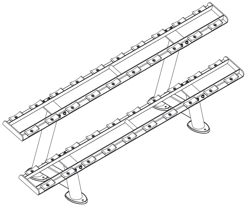
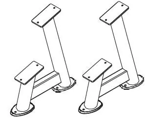
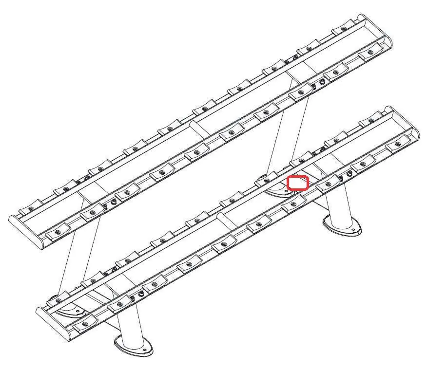
- Step 1: Attach one placing frame (2) to the lower floor standers (1) using eight screws (6), eight spring washers (9), and eight washers (8).
- Step 2: Attach the second placing frame (2) to the upper floor standers (1) using the remaining eight screws (6), eight spring washers (9), and eight washers (8).
- Finalization: Loosely screw all parts together first to ensure proper fit, then tighten all screws securely.
Maintenance and Care
To maintain the equipment and ensure safety:
- Cleaning: Clean the equipment with a damp towel (no solvents) after each training session to remove body sweat.
- Inspection: Regularly inspect screw connections. Perform a monthly inspection of all connections.
- Repairs: Immediately replace damaged or worn components. Use only original spare parts.
Troubleshooting
If you encounter issues, refer to the following:
- Squeaking or cracking noises: Check or lubricate screw connections using a grease-free silicone oil or spray.
- Unit wobbles: Ensure the unit is on even ground and tighten all screw connections.
Technical Data
- Max load: 380 kg per level / 760 kg total.
- Set-up dimensions: 228 cm x 65 cm x 80 cm.
- Net weight: 66.5 kg.
- Use class: S (Professional/Commercial).
Manufacturer information
Taurus Group
Practical help
Common problems
Squeaking & cracking noises
Check or lubricate screw connections with grease-free silicone oil or spray.
Unit wobbles
Ensure the floor is even and tighten all screw connections.
Before use
- Ensure assembly is performed by at least two adults.
- Verify all parts are included in the scope of delivery.
- Ensure the floor is flat, loadable, and solid.
- Verify there is enough free space around the equipment.
- Tighten all screws securely after initial loose assembly.
Specs in practice
- Set-up dimensions
- 228 cm x 65 cm x 80 cm.
Images and diagrams
- Exploded drawing shows the assembly of floor standers and placing frames.
- Parts list details screws, washers, and nuts required for assembly.
Model compatibility
- Suitable for home, semi-professional, and commercial use.

Manual page author
Michael Turner
Technical manual editor
Reviews PDF manuals for structure, safety notes, and practical product details so readers can find the right information quickly.