Electronics / Smart Trackers
User Manual for Teltonika FMC150 Advanced Tracker
Quick guide for the Teltonika FMC150 Advanced Tracker. Learn how to install the SIM card, connect the battery, configure the device via USB or SMS, and understand LED status indicators and wiring schemes.
Table of contents
Manual images
Click an image to enlargeQuick guide from the manual
The Teltonika FMC150 is an advanced tracker with CAN data reading features. This manual provides essential instructions for setting up, configuring, and installing the device. Before starting, ensure you have a plastic pry tool for cover removal and a compatible Micro-SIM card with the PIN request disabled.
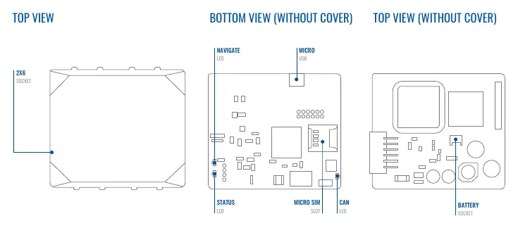
Know your device
The device features a 2x6 socket for wiring, a Micro-SIM slot, a Micro-USB port for configuration, and a battery socket. Status, Navigate, and CAN LEDs provide visual feedback on the device's operational state.
Installation
To prepare the device for use:
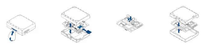
- Cover Removal: Gently remove the FMC150 cover using a plastic pry tool from both sides.
- SIM Card: Insert the Micro-SIM card into the slot, ensuring the cut-off corner points forward.
- Battery: Connect the battery to the device, positioning it so it does not obstruct other components.
- Closing: After configuration, reattach the device cover.
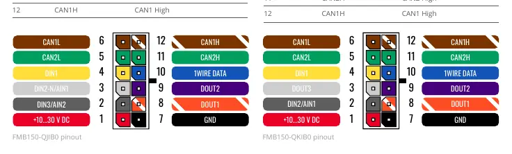
Wiring and Pinout
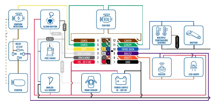
The device supports two wiring schemes (FMC150-QJIB0 and FMC150-QKIB0). The 12-pin connector handles power supply (10-30V DC), digital/analog inputs, digital outputs, and CAN bus connections. Always ensure wires are fastened to non-moving parts and avoid heat-emitting objects. Use a 3A, 125V external fuse for the power source.
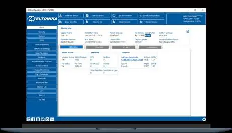
Configuration
The device can be configured via PC or SMS:

- PC Connection: Connect via Micro-USB or Bluetooth. For USB, install the TeltonikaCOMDriver.exe. Use the Teltonika Configurator software on Windows to manage settings, update firmware, and view status.
- SMS Configuration: Send an SMS command to the device with the format: setparam 2001:APN;2002:APN_username;2003:APN_password;2004:Domain;2005:Port;2006:0. Ensure two space symbols are inserted before the SMS text.
LED Indications
The device uses three LEDs to indicate status:
- Navigation LED: Indicates GNSS signal status (e.g., blinking every second means normal mode).
- Status LED: Indicates modem activity and sleep modes.
- CAN LED: Indicates CAN data reading status.
Technical Specifications
Key specifications include:
- Input Voltage: 10-30V DC with overvoltage protection.
- Operating Temperature: -40°C to +85°C (without battery).
- Ingress Protection: IP41.
- Memory: 128MB internal flash memory.
- Bluetooth: 4.0 + LE.
Safety Information
The device must be installed by qualified personnel. It is susceptible to water and humidity. Do not disassemble the device if damaged. Ensure the device is firmly fastened in a predefined location and disconnected from the vehicle before unmounting.
Official resources from the manual
Practical help
Common problems
Device not connecting to PC via USB
Ensure the TeltonikaCOMDriver.exe is installed and the device is powered with 10-30V DC.
SIM card not detected
Verify the Micro-SIM card is inserted with the cut-off corner pointing forward to the slot.
LEDs not blinking
Check the power supply connection (10-30V DC) and ensure the device is not in sleep mode.
Before use
- Use a plastic pry tool to open the device cover.
- Disable the PIN request on the Micro-SIM card.
- Ensure the power supply is between 10V and 30V DC.
- Download the latest Teltonika Configurator software.
- Install the required USB drivers on your Windows PC.
Specs in practice
- Input Voltage
- 10-30V DC with overvoltage protection.
- Operating Temperature
- -40°C to +85°C (without battery).
- Ingress Protection
- IP41 rating, indicating protection against solid objects over 1mm and dripping water.
Images and diagrams
- The pinout diagram details the 12-pin connector layout for both QJIB0 and QKIB0 models.
- Wiring schemes illustrate connections for ignition, fuel gauge, buzzer, and CAN bus.
Model compatibility
- FMC150-QJIB0 and FMC150-QKIB0 have different digital/analog input configurations.
- The device is not designed as a navigational device for boats.

Manual page author
Michael Turner
Technical manual editor
Reviews PDF manuals for structure, safety notes, and practical product details so readers can find the right information quickly.