Electronics / Positioning Systems
User Manual for Teltonika FMM130 Vehicle Tracker
Quick guide for the Teltonika FMM130 vehicle tracker. Includes wiring diagrams, installation steps, configuration via SMS or PC, and technical specifications.
Table of contents
Manual images
Click an image to enlargeQuick guide from the manual
This document provides essential information for the Teltonika FMM130 vehicle tracker. It covers device setup, wiring, configuration, and technical specifications. Always ensure the device is installed by qualified personnel and follows the safety guidelines provided.
Device Overview
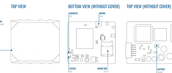
The FMM130 features a 2x6 socket for connectivity, a Micro-SIM slot, a battery socket, and status/navigation LEDs. The device is designed for vehicle tracking and telematics applications.
Installation and Wiring
Proper installation is critical for device performance. Follow the wiring scheme carefully:
- Power Supply: Connect to 10-30V DC. Use a 3A, 125V external fuse.
- Ignition: Ensure the ignition wire maintains power when the engine is running.
- Ground: Connect to the vehicle frame or metal parts fixed to the frame.
- Wiring: Fasten wires to non-moving parts and avoid heat sources.
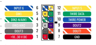
Refer to the Pinout section for specific channel assignments, including digital inputs, digital outputs, and 1-Wire data connections.
Setup and Configuration
To prepare the device for use:
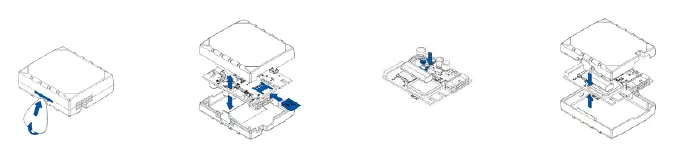
- Cover Removal: Use a plastic pry tool to gently remove the top cover.
- SIM Card: Insert the Micro-SIM card with the cut-off corner pointing forward. Ensure PIN request is disabled.
- Battery: Connect the internal battery.
- Cover: Reattach the cover after configuration.
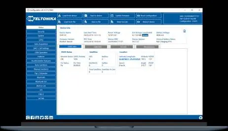
PC Configuration: Connect the device to a Windows PC using a Micro-USB cable or Bluetooth. Install the Teltonika COM port drivers and use the Teltonika Configurator software to adjust settings.
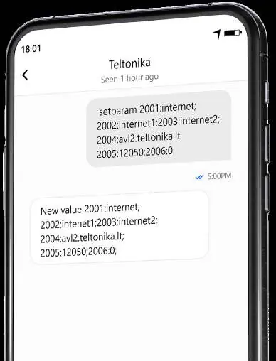
SMS Configuration: You can quickly configure the device by sending an SMS command. Ensure two space symbols are inserted before the SMS text. Example: setparam 2001:APN;2002:APN_username;2003:APN_password;2004:Domain;2005:Port;2006:0
LED Indications
The device features two LEDs to indicate status:
- Navigation LED: Indicates GNSS signal status.
- Status LED: Indicates modem activity and sleep mode status.
Technical Specifications
- Power: 10-30V DC input.
- Operating Temperature: -20°C to +85°C (without battery).
- Inputs/Outputs: 3 Digital Inputs, 3 Digital Outputs, 1 Negative Input, 2 Impulse Inputs.
- Connectivity: LTE CAT M1, GSM, GNSS, Bluetooth 4.0 + LE.
Safety Information
Do not disassemble the device. Ensure it is installed in a zone of limited access. The device is not designed for marine navigation. Dispose of batteries according to local regulations.
Practical help
Common problems
Device not connecting to network
Check SIM card installation, ensure PIN request is disabled, and verify GPRS/APN settings.
LEDs not blinking
Verify power supply (10-30V DC) and ensure wiring connections are secure.
Cannot connect via USB
Download and install the Teltonika COM port drivers from the official website.
Before use
- Ensure SIM card PIN request is disabled.
- Verify power supply is 10-30V DC.
- Install Teltonika Configurator software on Windows.
- Download and install COM port drivers.
- Ensure proper wiring according to the pinout diagram.
Specs in practice
- Input voltage
- 10-30V DC with overvoltage protection.
- Operating temperature
- -20°C to +85°C (without battery) for standard operation.
- Digital Inputs
- 3 inputs available for sensor monitoring.
- Digital Outputs
- 3 open collector outputs for controlling external devices.
Images and diagrams
- Pinout diagram shows the 12-pin connector layout for power, inputs, and outputs.
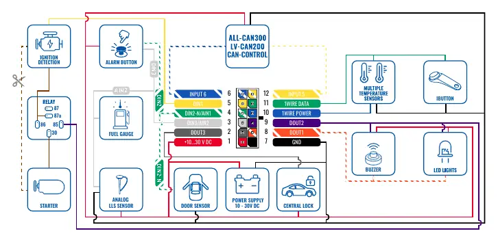
- Wiring scheme illustrates connections for ignition, fuel gauge, and sensors.
Model compatibility
- Supports 1-Wire devices.
- Compatible with Bluetooth peripherals like temperature sensors and OBDII dongles.

Manual page author
Michael Turner
Technical manual editor
Reviews PDF manuals for structure, safety notes, and practical product details so readers can find the right information quickly.