HVAC / Packaged Rooftop Units
Installation and Maintenance Manual for Temperzone OPA 1410/2110 RLTM1FPQ Air Cooled Packaged Units
Comprehensive installation and maintenance guide for Temperzone OPA 1410/2110 RLTM1FPQ Econex air-cooled packaged units. Includes wiring diagrams, commissioning steps, UC8 controller settings, and troubleshooting procedures.
Quick answers from the manual
Quick answer
- The OPA 1410/2110 RLTM1FPQ is an air-cooled packaged unit using R32 refrigerant. It is managed by the UC8 controller, which handles system protection and capacity control. Installation requires proper mounting, electrical connection by a qualified professional, and a 4-hour crankcase heater delay before initial compressor start. p. 1, 4
Key actions
- Commissioning the unit p. 5
- Setting fan speed p. 4, 5
First start
- Remove shipping wedges p. 2, 4
- 4-hour delay p. 4
Show 4 more answers Show less
Problems and fixes
Unit locked out
Reset via SW3 button, Modbus command, or power cycle.
p. 8Maintenance and reset
- Resetting locked-out unit p. 8
Technical specifications
| Parameter | Value | Meaning | Pages |
|---|---|---|---|
| Refrigerant | R32 | Mildly flammable refrigerant | p. 1 |
Where to find it in the PDF
- General & Installation p. 1, 2
- Wiring & Control p. 2, 3, 4
- Maintenance & Troubleshooting p. 6
Table of contents
Manual images
Click an image to enlargeQuick Guide from the Manual
This document provides installation and maintenance instructions for the Temperzone OPA 1410/2110 RLTM1FPQ Econex air-cooled packaged units. Important: These units use R32 refrigerant (Class A2L), which is mildly flammable. Ensure installation occurs in a well-ventilated space away from ignition sources. Before starting the compressors, a four-hour delay is required to allow crankcase heaters to drive liquid refrigerant out of the oil.
Installation
Units must be installed in accordance with national and regional regulations. Ensure adequate service access and clearances as specified in the product specification sheet. If placing units side-by-side, allow at least 2m between coil faces.
- Mounting: Fasten the unit to a firm, flat horizontal base. If on a roof, use a substantial structure with vibration-isolating pads. If on the ground, use rubber pads to provide at least 20mm ground clearance.
- Pallet Removal: Remove wooden pallets from beneath mounting rails by temporarily removing drain troughs.
- Condensate Drains: Must be 'U' trapped outside the unit with a vertical height of at least 100mm and a slope of at least 1 in 50.
Wiring
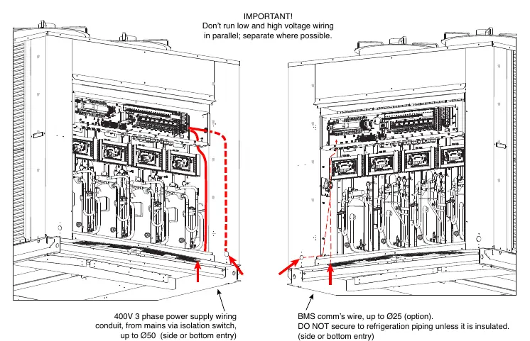
Electrical work must be performed by a qualified electrician in accordance with AS/NZS 3000. The unit must be wired directly from a distribution board using an appropriately sized circuit breaker. An isolating switch is required near the unit.
Control Options
The unit can be controlled via:
- TZT-100 wall thermostat
- 24V AC and 0-10V signals from an external controller
- Remote on/off switch
- Modbus RTU serial communications
- BACnet-IP serial communications (with optional gateway)
Start-up Procedure
Before starting, ensure all shipping wedges are removed from beneath the compressors. Perform a check of electrical connections, air filters, and fan motor rotation. After applying power, perform air balancing. Before starting compressors, ensure the 4-hour crankcase heater delay is complete.
Commissioning
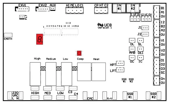
Place all UC8 controllers in commissioning mode by pressing and holding the SW3 push button until the display shows 'c'. This reduces waiting times for the next 30 minutes.
Maintenance
- Monthly: Check air filters (clean or replace), check condensate drain for free drainage, and inspect compressor compartment for oil stains.
- Six Monthly: Check tightness of electrical connections, inspect for corrosion in high salt atmospheres, and check fan motor mountings.
- Yearly: Check refrigerant piping for chafing/vibration, inspect air supply at diffusers, check for excessive noise/vibration, and clean outdoor coil fins.
Troubleshooting
If the unit displays an error code, refer to the UC8 Controller label or the Temperzone Service Tools app. Common issues include:
- Unit locked out: Reset via SW3 button, Modbus command, or power cycle.
- Heating not delivered: Check design conditions and de-icing cycles.
- Water leakage: Check drain trap/vent/slope and reduce max fan speed if water carry-over occurs.
Practical help
Common problems
Unit leaking water
Check drain trap, vent, and slope. If water carry-over occurs, reduce maximum fan speed.
Heating not delivered when needed
Check design conditions, ensure outdoor ambient temperature is within limits, and verify de-icing cycles.
Unit locked out
Check fault code on UC8 display. Reset via SW3 button, Modbus command, or by removing mains power for at least 3 seconds.
Before use
- Remove shipping wedges from beneath each compressor
- Check tightness of all electrical connections
- Ensure air filters are correctly installed
- Verify supply voltage between each phase and neutral
- Ensure indoor fan motors can rotate freely
Show more Show less
Specs in practice
- R32 Refrigerant
- Mildly flammable (Class A2L); requires well-ventilated installation and storage.
- UC8 Controller
- Main unit controller managing system protection, safety timers, and capacity control.
- Safety Timers
- Minimum off time 3 minutes; minimum run time 1.5 minutes.
Images and diagrams
- UC8 Controller layout showing inputs, outputs, and display
- Condensate drain 'U' trap configuration
- Wiring paths for power and BMS communication
Model compatibility
- Compatible with TZT-100 wall thermostat
- Supports Modbus RTU and BACnet-IP communication
- Requires qualified electrician for installation

Manual page author
Michael Turner
Technical manual editor