Automotive / RV Caravan Accessories
User Manual for Thule Single Step V15
Quick guide for installing and operating the Thule Single Step V15. Includes wiring diagrams, mechanical installation steps, and manual release procedures for your RV step.
Table of contents
Manual images
Click an image to enlargeQuick guide from the manual
The Thule Single Step V15 is a 12V electric step designed for RVs and caravans. This manual provides essential instructions for mechanical installation, electrical wiring, and emergency operation. Always ensure the step is mounted securely and the electrical system is protected by a 20A fuse.
Content and Tools
Before starting, ensure you have all necessary parts and tools:
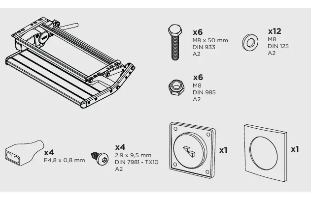
- Parts included: M8x50mm bolts (x6), M8 nuts (x6), M8 washers (x12), and mounting hardware.
- Tools required: 13mm wrench, drill with 9mm and 48mm bits, and a TX10 screwdriver.
Installation
The mechanical installation involves securing the step frame to the vehicle chassis.
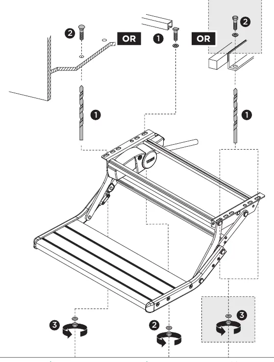
- Position the step frame according to the vehicle's mounting points.
- Drill 9mm holes as required for the M8 bolts.
- Secure the frame using the provided M8 bolts, washers, and nuts. Ensure the assembly is rigid and stable.
Electrical Installation
The step operates on a 12V DC system. Proper wiring is critical for safe operation.
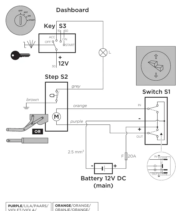
- Wiring: Connect the motor wires (Purple and Orange) to the switch and the 12V battery source.
- Fuse: A 20A fuse must be installed in the circuit.
- Optional Relay: For automatic retraction, an optional relay (308200) can be installed. Refer to the wiring diagram for specific connections.
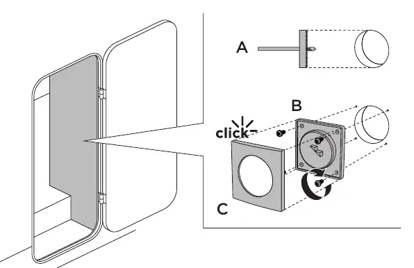
- Switch: Install the switch in a convenient location using a 48mm hole.
Operation
To operate the step:
- Open/Close: Press and hold the switch for 2-3 seconds to extend or retract the step.
Manual Release
In case of electrical failure, the step can be operated manually:
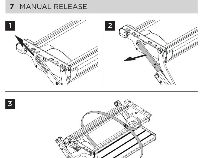
- Locate the manual release mechanism on the step assembly.
- Follow the steps illustrated in the manual to disengage the motor and manually move the step to the desired position.
Manufacturer information
Thule
Practical help
Common problems
Step does not extend or retract
Check the 12V power supply, ensure the 20A fuse is intact, and verify all wiring connections are secure.
Automatic retraction not functioning
Verify that the optional relay (308200) is correctly installed and wired according to the diagram.
Before use
- Verify 12V power source is connected.
- Ensure a 20A fuse is installed in the circuit.
- Check that the step is mounted securely using the provided M8 bolts.
- Confirm wiring colors (Purple/Orange) match the diagram.
- Test the switch operation before finalizing installation.
Images and diagrams
- The wiring diagram illustrates the connection between the battery, switch, motor, and optional relay.
- Mechanical diagrams show the bolt placement and drilling points for the step frame.
Model compatibility
- Designed for RV and caravan use.
- Optional relay (308200) is required for the automatic retraction feature.

Manual page author
Emily Carter
User documentation editor
Prepares concise manual descriptions and highlights the most useful setup, operation, and maintenance information for readers.