Automotive / RV Caravan Accessories
Thule Slide Out G2 12V Step
Comprehensive installation and user guide for the Thule Slide Out G2 12V step. This manual covers mounting procedures, 12V electrical wiring diagrams, operation, maintenance, and manual release instructions.
Table of contents
Manual images
Click an image to enlargeQuick Guide
This document provides installation and operation instructions for the Thule Slide Out G2 12V step. Key tasks include mounting the step to the vehicle chassis, connecting the 12V electrical system, and performing regular maintenance. Always ensure the step path is clear before operation.
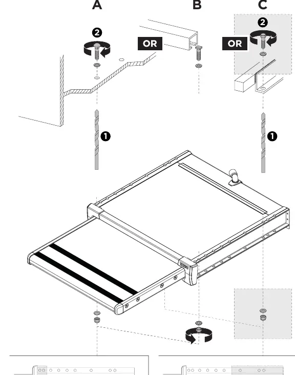
Installation
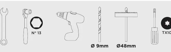
The installation requires specific tools: a N° 13 wrench, a Ø 9mm drill, a Ø 48mm hole saw, and a TX10 screwdriver. The step is mounted using M8 bolts, nuts, and washers. Ensure the step is securely bolted to the vehicle frame according to the provided diagrams.
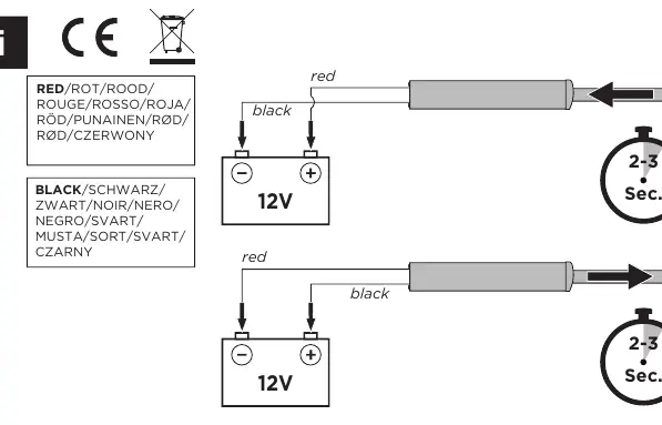
Electrical Installation
The step operates on a 12V DC system. Connect the red wire to the positive (+) terminal and the black wire to the negative (-) terminal. A 20A fuse is required in the circuit. The manual includes detailed wiring diagrams for standard operation, as well as configurations for a warning lamp/buzzer and an optional relay for automatic retraction.
Operation
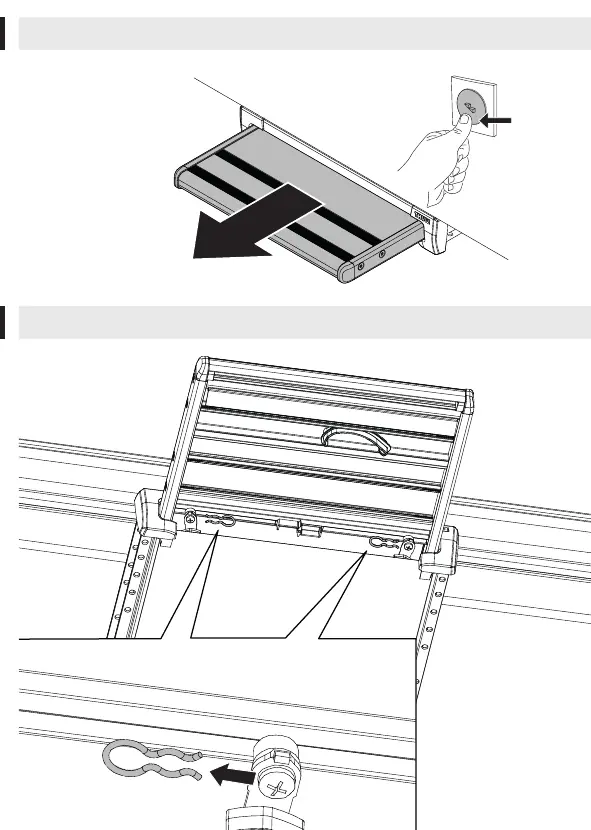
The step is operated via an electrical switch. Press the switch to extend or retract the step. Ensure the step is fully retracted before driving the vehicle.
Maintenance
Regular maintenance is required to ensure smooth operation. This includes cleaning the step mechanism and checking for debris. If the step becomes stuck, use the manual release procedure to retract it.
Manual Release
In case of electrical failure, the step can be operated manually. Follow the steps outlined in the manual to disengage the motor and manually move the step.
Manufacturer information
Thule
Practical help
Common problems
Step does not extend or retract
Check the 12V power supply, verify wiring connections, and ensure the 20A fuse is intact.
Step is stuck
Use the manual release procedure to disengage the motor and manually retract the step.
Before use
- Verify 12V power source is connected correctly (Red +, Black -).
- Ensure all mounting bolts (M8) are tightened securely.
- Check that the step path is clear of obstacles.
- Verify the 20A fuse is installed in the circuit.
- Test the step extension and retraction before driving.
Images and diagrams
- Wiring diagrams show connections for standard 12V setup, warning lamp/buzzer, and optional relay for automatic retraction.
- Installation diagrams detail the mounting points and bolt placement.
Model compatibility
- Designed for RV/Caravan installation.
- Compatible with optional electronic control unit (308812).
- Compatible with optional relay for automatic retraction (308200).

Manual page author
Michael Turner
Technical manual editor
Reviews PDF manuals for structure, safety notes, and practical product details so readers can find the right information quickly.