HVAC / HVAC Systems
Trane 8 Port Distribution Board Installation Guide
Official installation guide for the Trane 8 Port Distribution Board. Includes wiring diagrams, transformer isolation instructions, and safety precautions for HVAC zoning systems.
Quick answers from the manual
Quick answer
- The 8X Distribution Board is designed to isolate transformer loads in HVAC zoning systems. It provides eight connection points for Link communication and 24-volt power, with specific port assignments to ensure proper system operation. p. 3, 4
Key actions
- Connect the Indoor Unit only to Port 8. p. 4
- Do not ground the secondary side of the second transformer. p. 4
Technical specifications
| Parameter | Value | Meaning | Pages |
|---|---|---|---|
| Transformer Requirement | 50VA | Required for furnaces when incorporating an electronic air cleaner. | p. 3, 4 |
Where to find it in the PDF
- General Information p. 3
- Component Wiring p. 3
- 8X Distribution Board p. 4
Table of contents
Manual images
Click an image to enlargeImportant Information
This guide provides installation instructions for the Trane 8 Port Distribution Board. Proper application is critical when installing zoning systems to ensure the HVAC system provides the expected comfort. This document is intended for use by individuals with adequate electrical and mechanical experience.
Safety Precautions
WARNING: This product contains live electrical components. During installation, testing, servicing, and troubleshooting, it may be necessary to work with live electrical components. Failure to follow all electrical safety precautions could result in death or serious injury.
General Information
The 8X distribution board is required to isolate transformer loads in HVAC zoning systems. This wiring technique separates system loads from zoning loads, allowing each transformer to control dedicated components.
- The indoor unit, outdoor unit, and air cleaner should be powered from the indoor unit transformer.
- Furnaces require the installation of a 50VA transformer when incorporating an electronic air cleaner.
- Link control components (system controller, thermostat, and zone panels) are controlled through the secondary transformer.
- The transformer that powers the zone panels also powers the dampers.
Component Wiring
Control wiring is more challenging if a secondary transformer is needed. The 8X distribution board is required to isolate these transformer loads.
8X Distribution Board Installation
The board provides eight connection points for Link communication and the 24-volt power source.
- Port 8: Dedicated header for the Indoor Unit connection. This port is used for transformer isolation.
- Ports 1-7: Used to control devices from the second transformer load.
- Communication: The bottom left header must be connected to the communication circuit from the indoor unit transformer whenever the calculated load requires a second transformer.
Important Notes:
- The 24V R is not connected to port 8. This break in R eliminates the need for transformer phasing.
- Since the two 24VAC transformers are isolated, phasing is not a concern.
- Do not ground the secondary side of the second transformer.
- Leave this secondary voltage floating.
Practical help
Common problems
Transformer phasing concerns
The board design isolates the two 24VAC transformers, so phasing is not a concern.
Grounding the secondary side
Do not ground the secondary side of the second transformer; leave the secondary voltage floating.
Before use
- Verify that all installation phases comply with national, state, and local codes.
- Ensure the indoor unit, outdoor unit, and air cleaner are powered from the indoor unit transformer.
- Install a 50VA transformer if the furnace incorporates an electronic air cleaner.
- Connect the indoor unit only to Port 8.
- Ensure all Link control components are connected to the secondary transformer.
Specs in practice
- 50VA Transformer
- Required for furnaces when incorporating an electronic air cleaner.
Images and diagrams
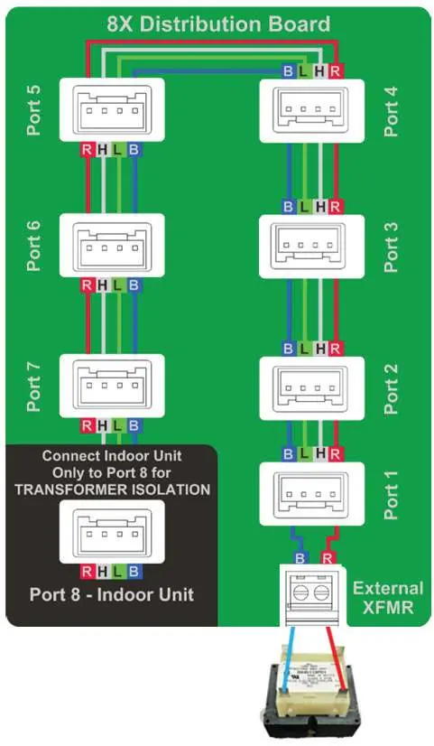
- The wiring diagram illustrates the 8X Distribution Board with ports 1-7 for control devices and port 8 specifically for the Indoor Unit.
- The diagram shows the connection points for the External XFMR (Transformer) and the isolation path for the Indoor Unit.
Model compatibility
- Compatible with Link technology control components including system controllers, thermostats, and zone panels.

Manual page author
David Miller
Documentation analyst
Organizes user manual content into clear summaries, with attention to model details, product context, and everyday usability.