HVAC / Thermostats & Controls
Trane Gas Heat Exchanger Replacement Installation Guide
Installation guide for replacing the gas heat exchanger in Trane Precedent A cabinet units. Includes safety warnings, required tools, parts list, and step-by-step replacement procedures.
Table of contents
Manual images
Click an image to enlargeQuick guide from the manual
This document provides instructions for replacing the gas heat exchanger in Trane Precedent A cabinet units (3 to 5 tons). Only qualified personnel should perform this service. The procedure requires specific tools, including 5/16-inch nut drivers and high-temperature RTV silicone. Ensure all electrical and gas supplies are disconnected before starting.
Safety Warnings
- Qualified Personnel Only: Installation and servicing must be performed by trained professionals. Improper installation can result in death, serious injury, or equipment damage.
- Personal Protective Equipment (PPE): Technicians must wear appropriate PPE, including cut-resistant gloves, safety glasses, and arc flash clothing when working with energized electrical components.
- Flammable Refrigerant: This equipment uses R-454B (A2L) refrigerant. Use only R-454B rated service equipment and components.
- Hazardous Gases: Ensure proper installation to prevent flammable mixtures or carbon monoxide leaks.
Tools and Parts
Tools Required
- 5/16-inch Nut Driver
- 5/16-inch Nut Long Driver (12 to 15-inch)
- 5/16-inch Ratchet and Extension
- Blade/Cutter
- Tube of RTV (Maximum temperature rating of 500°F)
Parts List
- Gas Heat Exchanger
- Rear 0.88 ID Tube Foam Block Enclosure
- Tube Insulation (7/8 in. OD x 3/8 in. Thick x 18 in. Long)
Replacement Procedures
Removal
- Shut off all electrical power and gas service to the unit.
- Disconnect condensate drain piping.
- Remove all access panels, front center posts, and the rear duct cover.
- If configured for horizontal supply, remove the connecting ductwork.
- Remove the condensate drain pan.
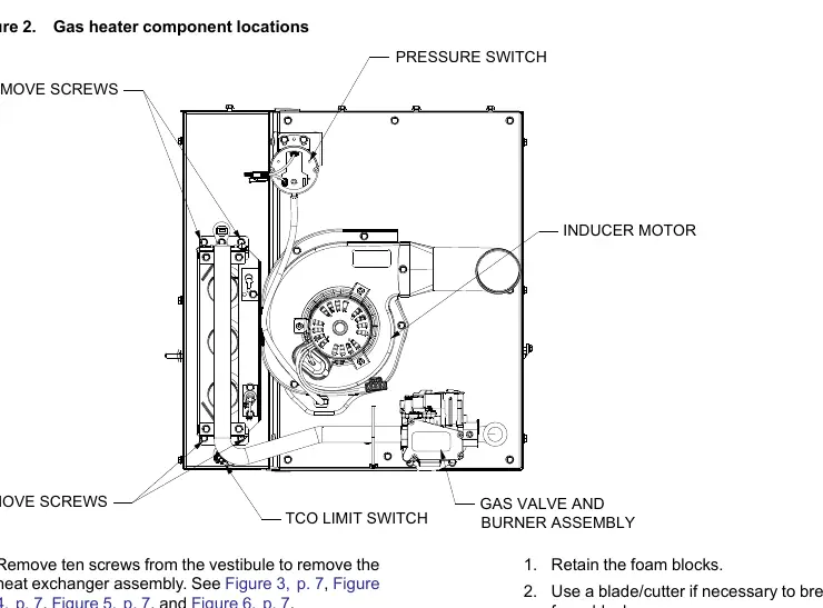
- Disconnect wires from components in the gas heat compartment (TCO1, Pressure Switch, Gas Valve, etc.) and route them out through harness routing holes.
- Remove the high voltage spark ignition wire from the igniter and the pressure switch orange silicone hose.
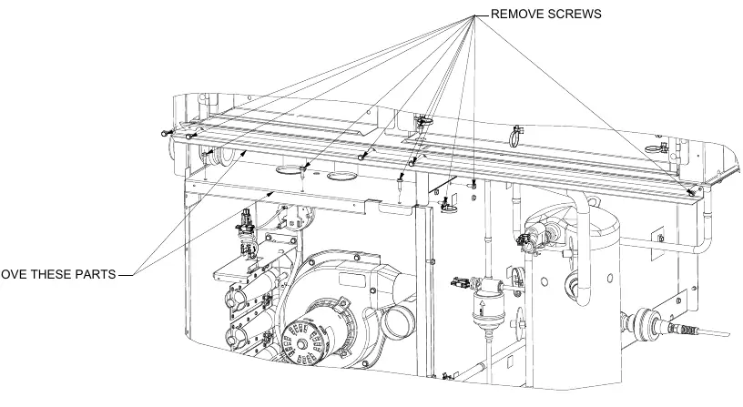
- Open the control box access panel and remove the specified sheet metal parts.
- Remove the gas valve, manifold tube, burner assembly, TCO1 limit, pressure switch, and inducer motor.
- Remove the air orifice (retain for reinstallation).
- Remove the ten screws from the vestibule to access the heat exchanger assembly.
- Remove foam blocks covering refrigeration tubes to access top screws.
- Remove the unit roof to access the fourth screw.
- Remove the heat exchanger support rod if necessary.
- Using two people, push the heat exchanger out from the rear supply duct through the front of the unit.
Installation
- Install the new heat exchanger by feeding it through the front of the unit with two people.
- Align the heat exchanger from the rear duct opening.
- Verify the heat exchanger catches the support rod between the bottom primary tube and the tube directly above it.
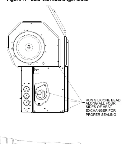
- Seal the heat exchanger with a bead of high-temperature silicone.
- Use field-supplied tube insulation to cover exposed rear side refrigeration tubes and secure with cable ties.
- Reinstall sheet metal parts.
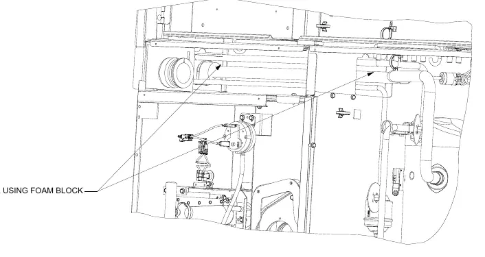
- Seal gaps using the rear foam block cut into 0.5-inch thick pieces to prevent air leakage.
- Use the front foam block to cover front tubes.
- Reassemble the unit by reversing the removal steps.
Practical help
Common problems
Flammable Refrigerant Handling
The unit uses R-454B (A2L) refrigerant. Use only R-454B rated service equipment and components.
Air Leakage
Ensure all gaps around tubes are sealed using the provided foam blocks (cut to 0.5-inch thickness) and high-temperature silicone.
Hazardous Gas Exposure
Improper installation can lead to carbon monoxide or flammable mixtures. Follow all setup instructions precisely.
Before use
- Shut off all electrical power to the unit.
- Shut off and disconnect gas service.
- Verify all required PPE is available (cut resistant gloves, safety glasses, arc flash clothing).
- Ensure 5/16-inch nut drivers and extensions are available.
- Obtain RTV silicone with a 500°F temperature rating.
Specs in practice
- RTV Silicone
- Must be rated for a maximum temperature of 500°F.
Images and diagrams
- Component Locations: Identifies the gas valve, burner assembly, inducer motor, pressure switch, and TCO limit switch.
- Sealing: Shows the application of a silicone bead along all four sides of the heat exchanger for proper sealing.
- Foam Blocks: Illustrates where to place foam blocks to prevent air leakage.
Model compatibility
- Compatible with Precedent A cabinet, 3 to 5 tons, Gas heat models.

Manual page author
Emily Carter
User documentation editor
Prepares concise manual descriptions and highlights the most useful setup, operation, and maintenance information for readers.