HVAC / HVAC Systems
Installation Instructions for Trane 18-AD49D1-1A Multi-Position Cased Coils
Comprehensive installation guide for Trane 18-AD49D1-1A Multi-Position Cased Coils. Includes safety precautions, R454B refrigerant leak mitigation kit setup, piston and TXV installation, ductwork requirements, and drain piping instructions.
Quick answers from the manual
Quick answer
- This manual provides installation instructions for Trane 18-AD49D1-1A Multi-Position Cased Coils, including mandatory setup for the R454B refrigerant leak mitigation kit, piston/TXV installation, and ductwork requirements. p. 1, 9, 18
Key actions
- Install the leak mitigation kit on the front or side of the coil. p. 18
- Connect the refrigerant sensor to the leak mitigation control kit. p. 13, 20
First start
- Ensure the unit is properly grounded and all electrical connections are secure. p. 4, 15
- Verify the refrigerant sensor is correctly installed and powered. p. 9, 11
Problems and fixes
Refrigerant sensor communication fails
Check sensor wiring and communication; contact manufacturer if faulty.
p. 19Maintenance and reset
- Replace the refrigerant sensor after its 15-year service life. p. 11
Technical specifications
| Parameter | Value | Meaning | Pages |
|---|---|---|---|
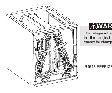
| Refrigerant | R454B | Class A2L mildly flammable refrigerant. | p. 8 |
Where to find it in the PDF
- Safety Information p. 3, 4, 5, 6
- Installation p. 10, 11, 12, 13
Table of contents
Manual images
Click an image to enlargeQuick guide from the manual
This document provides essential installation and safety instructions for the Trane 18-AD49D1-1A Multi-Position Cased Coils. This unit is designed for use with R454B refrigerant, which is classified as mildly flammable (A2L). A factory-installed leak mitigation kit is required for operation. Installation must be performed by qualified, licensed HVAC service personnel.
Safety Precautions
Warning: This unit uses R454B refrigerant. Failure to follow safety protocols can result in fire, explosion, or serious injury. Always ensure the area is well-ventilated during installation and service. The unit must be permanently grounded. Do not use open flames or ignition sources near the unit. Personal Protective Equipment (PPE) is mandatory for all technicians.
Installation and Trap Connection
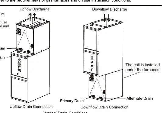
The coil can be positioned for bottom return air in upflow and horizontal right applications, or top return in downflow and horizontal left applications. Ensure the coil is leveled and the gap between the coil and furnace is sealed with sheet metal or appropriate material to prevent air leaks. Secure the coil case to the furnace using self-tapping screws, ensuring they do not damage the coil or drain pan.
Leak Mitigation Kit
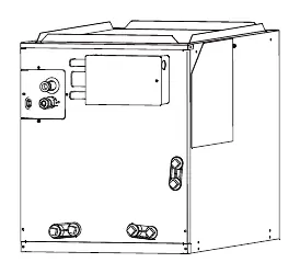
The R454B refrigerant leakage sensor is pre-configured on the coil. The leak mitigation control kit must be installed on the front or side of the coil. Ensure the sensor wire is connected to the control board. If the sensor detects a leak, the system will automatically shut down the outdoor unit, force the blower to maximum speed, and disable gas heating for 5 minutes.
Piston and TXV Installation
The unit comes with a factory-installed piston metering device. Check Table 4-1 to verify if the pre-installed piston matches your system combination. If a different size is required, remove the pre-installed piston and install the correct one from the accessory pack. If using an optional TXV kit, follow the specific instructions provided with the kit and ensure proper brazing and connection.
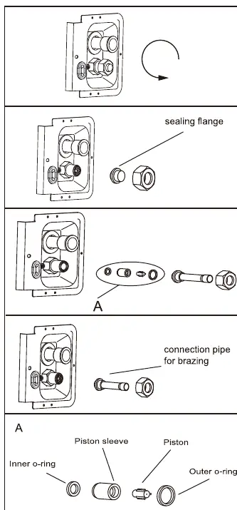
Refrigerant Line and Ductwork
Keep coil connections sealed until ready for brazing. Use a wet rag to protect rubber grommets and seals from torch flames. After brazing, perform a pressure test with inert gas and a vacuum test. Ductwork must comply with NFPA 90A and 90B standards. Ensure the supply plenum is attached to the 3/4-inch duct flanges supplied with the unit.
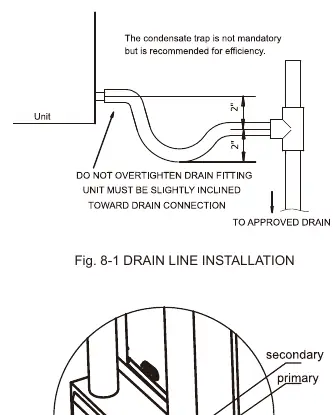
Drain Application
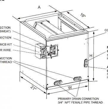
The drain pan includes primary and secondary drain connections. Use 3/4-inch NPT female fittings and hand-tighten to approximately 37 in-lb to avoid damaging the connection. Install a trap in the drain line below the bottom of the drain pan to ensure proper drainage.
Practical help
Common problems
Refrigerant sensor communication failure
Check wiring connections to the sensor and control board; ensure the sensor is not faulty.
Refrigerant leak detected
Immediately ventilate the area, shut down the system, and contact a professional technician.
Water blow-off from coil
Verify that the airflow setting does not exceed the maximum limits specified in Table 7-2.
Before use
- Verify the unit is permanently grounded.
- Ensure the leak mitigation kit is installed and connected.
- Check that the refrigerant sensor is in its original factory position.
- Confirm ductwork compliance with NFPA 90B.
- Ensure the drain line has a proper trap installed.
- Verify the piston size matches the system requirements.
Specs in practice
- Leak Mitigation Kit
- A mandatory safety system that monitors for refrigerant leaks and initiates emergency ventilation.
Images and diagrams
- Fig 2-1: Cased dimensions and component location.
- Fig 3-1: Installation of cased coil on furnace.
- Fig 3-6: Mounting section view for the leak mitigation kit.
- Fig 8-1: Proper drain line installation with trap.
Model compatibility
- Compatible with cooling and heat pump systems.
- Must be installed downstream of the furnace in furnace applications.
- Requires specific piston or TXV sizing based on the outdoor unit capacity.

Manual page author
Michael Turner
Technical manual editor
Reviews PDF manuals for structure, safety notes, and practical product details so readers can find the right information quickly.