HVAC / HVAC Systems
Installation Guide for Trane 18-BC113D1-1A Integrated Variable Speed Control Drive
A comprehensive installation and replacement guide for the Trane 18-BC113D1-1A Integrated Variable Speed Control Drive. This manual covers safety precautions, required tools, removal of the old drive, application of thermal grease...
Quick answers from the manual
Quick answer
- This guide provides instructions for replacing the Integrated Variable Speed Control (IVSC) drive, including safety procedures, removal of the old unit, application of thermal grease, and installation of the new drive. p. 1, 4, 6
Key actions
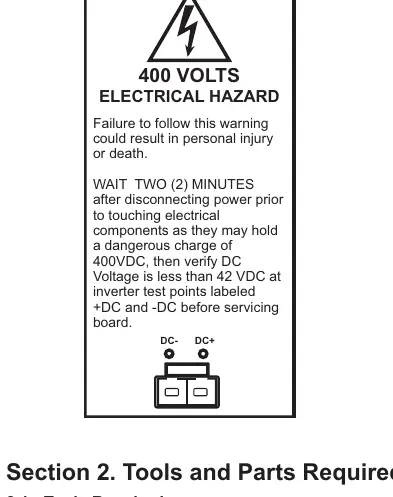
- Power down and wait 2 minutes before servicing. p. 4
- Verify DC voltage is less than 42VDC. p. 4
- Apply 1/8 inch bead of thermal grease. p. 6
- Tighten aluminum nuts to 40-50 in. lbs. p. 7
First start
- Start up unit and verify operation after final inspection. p. 7
Technical specifications
| Parameter | Value | Meaning | Pages |
|---|---|---|---|
| Torque | 40-50 in. lbs. | Tightening torque for aluminum nuts | p. 7 |
| Wait time | 2 minutes | Time to wait after power down | p. 4 |
Where to find it in the PDF
- Tools and Parts p. 3
- Remove IVSC p. 4, 5
- Reinstall IVSC p. 6, 7
Table of contents
Manual images
Click an image to enlargeImportant Information from the Manual
This document provides instructions for replacing the Integrated Variable Speed Control (IVSC) drive. Safety is critical: Only qualified personnel should perform this installation. Always disconnect all electric power and wait at least two minutes before touching electrical components to allow the 400VDC charge to dissipate. Verify that DC voltage is less than 42VDC before proceeding.
Tools and Parts Required
Before beginning, ensure you have the following tools:
- DC Volt Meter
- 5/16 inch Nut Driver
- 7/16 inch Socket Wrench
- Torque Wrench with 7/16 inch Socket
The replacement kit includes thermal grease and three aluminum nuts for the cold plate.
Removing the IVSC
- Power down the outdoor unit and wait at least 2 minutes.
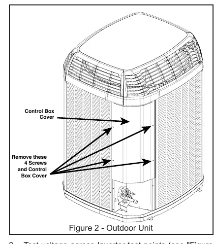
- Remove the 4 screws securing the control box cover.
- Test voltage across inverter test points (+DC and -DC) to ensure it is below 42VDC.
- Remove the P-Clamp securing the shielded wiring harness and disconnect the harness.
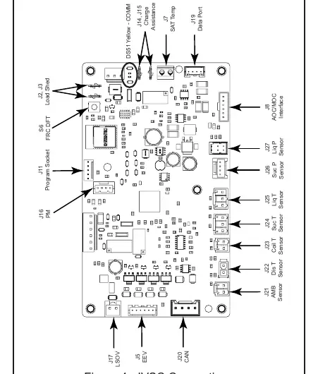
- Unplug all AOC connectors (Latching Switchover Valve, EEV, CAN, sensors, etc.) and HPCO wires.
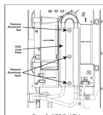
- Remove the three aluminum nuts securing the cold plate to the drive assembly.
- Remove the cold plate and wipe away existing thermal grease from copper tubes.
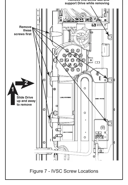
- Remove the screws securing the IVSC and slide the drive up and away from the cabinet housing.
Applying Thermal Grease and Reinstalling
Proper thermal contact is critical for the drive.
- Apply a small, 1/8 inch bead of thermal grease in the center of the cutout around the entire length.
- Place the drive back into the cabinet housing.
- Replace the top right screw first to secure the drive, then replace the remaining 5 screws.
- Reattach all wiring harnesses to the AOC and MOC boards.
- Align the liquid line with the cutout on the IVSC and seat the rubber grommet.
- Position the cold plate and hand-tighten the aluminum nuts.
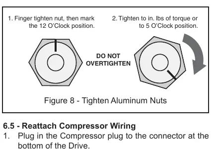
- Tighten the aluminum nuts to 40-50 in. lbs. of torque. Do not overtighten, as they are designed to strip at 80 in. lbs.
Final Inspection
Verify that all wires are reconnected and not pinched. Start the unit and verify operation. Replace the control box cover and ensure the line set cover is in place.
Practical help
Common problems
Hazardous voltage present
Wait at least 2 minutes after disconnecting power and verify DC voltage is less than 42VDC at test points before touching components.
Aluminum nuts stripping
Do not overtighten. Use a torque wrench set to 40-50 in. lbs. or use the 12 o'clock to 5 o'clock marking method.
Thermal grease application
Apply a 1/8 inch bead in the center of the cutout. The included tube contains enough for 2-3 applications.
Before use
- Verify you have a DC Volt Meter, 5/16 inch Nut Driver, 7/16 inch Socket Wrench, and Torque Wrench.
- Ensure the replacement kit contains thermal grease and 3 aluminum nuts.
- Disconnect all electric power and follow lockout/tagout procedures.
- Verify DC voltage is less than 42VDC at inverter test points.
- Ensure the liquid line is not bent or strained during removal.
Specs in practice
- Safe Voltage
- Less than 42 VDC.
Images and diagrams
- Figure 1: Shows the IVSC test points for +DC and -DC.
- Figure 4: Details the AOC/MOC connection points for sensors and harnesses.
- Figure 8: Illustrates the proper tightening procedure for aluminum nuts using a felt tip marker.
Model compatibility
- Use only the aluminum nuts that were on the unit originally or those that shipped with the Replacement Kit.

Manual page author
Emily Carter
User documentation editor
Prepares concise manual descriptions and highlights the most useful setup, operation, and maintenance information for readers.