Tools / Welding Equipment
User Manual for VEVOR Gas Welding and Cutting Torch Kit 1C020-0062 C
Quick guide for the VEVOR Gas Welding and Cutting Torch Kit (1C020-0062 C). Includes assembly instructions, safety guidelines, operation steps, and technical specifications.
Quick answers from the manual
Quick answer
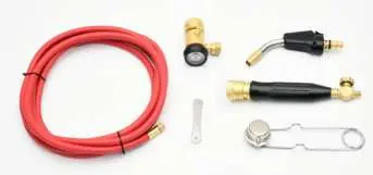
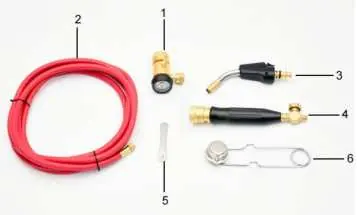
- The VEVOR Gas Welding and Cutting Torch Kit is used for brazing and soldering. Assembly requires connecting the regulator to the cylinder, attaching the hose (left-hand threads), and connecting the torch handle. Always perform a leak test with soapy water before operation. p. 5, 17, 28, 39
Key actions
- Check for leaks p. 4, 16, 27, 38
- Ignite the torch p. 6, 18, 29, 40
First start
- Assemble the kit, check for leaks, and adjust the regulator. p. 5, 17, 28, 39
Problems and fixes
Weak flame
Clean the orifice or replace the filter screen.
p. 6, 18, 29, 40Maintenance and reset
- Clean the orifice and filter screen. p. 6, 18, 29, 40
Technical specifications
| Parameter | Value | Meaning | Pages |
|---|---|---|---|
| Gas Flow | Varies by tip | Gas consumption rate | p. 8, 20, 31, 42 |
Where to find it in the PDF
- Safety Instructions p. 2, 3, 4, 13
- Assembly p. 5, 16, 27, 38
- Using the Torch p. 6, 18, 29, 40
- Specifications p. 8, 20, 31, 42
Table of contents
Manual images
Click an image to enlargeQuick Guide
This manual provides instructions for the VEVOR Gas Welding and Cutting Torch Kit. Before use, ensure you have read all safety instructions. The kit is designed for brazing and soldering. Always operate in a well-ventilated area and wear appropriate protective gear, including gloves and eye protection.
Safety Information
- Ventilation: Always use the torch in a well-ventilated area to avoid health hazards from fumes.
- Personal Protection: Wear gloves and eye protection (Number 3 shade recommended for brazing).
- Leak Testing: Check all connections for leaks using a soapy-water solution. Never use a flame to test for leaks.
- Storage: Do not store gas tanks in living areas, confined spaces, or near open flames/heat sources. Always store cylinders in an upright position.
- Handling: Do not drop the tank or torch. Do not leave a lit torch unattended.
Assembly
1. Check the cylinder valve and regulator inlet for contamination. Ensure threads are clean.

2. Securely attach the regulator inlet to the cylinder valve.
3. Attach the hose to the regulator outlet. Note that hose fittings are left-hand threads; do not overtighten.
4. Attach the torch handle to the hose using two wrenches (one on the hose nut, one on the handle valve body). Tighten counterclockwise.
5. Close the torch handle valve. Open the cylinder valve no more than 3/4 turns. Adjust the regulator screw clockwise.
Using the Torch
1. Inspect O-rings on the torch and handle for damage. Replace if necessary.
2. Insert the torch base into the quick disconnect until it clicks.
3. Open the torch handle valve at least one turn.
4. Press the trigger button to ignite. If it does not light, release and press again.
5. Do not throttle the torch down; operate at full flow to prevent overheating.
Maintenance
If the flame is weak, shut off the fuel, remove the torch, and use a pick to remove the O-ring and filter screen. Use a 1/8" Allen wrench to remove the orifice from the base. Clean the orifice or blow out contaminants with an air hose. Reassemble and test.
Technical Specifications
The kit includes various tips (e.g., 3A, 5A, 8A, 12A) with different gas flow rates and heat outputs (BTU). Refer to the specifications table in the manual for the specific tip size and application (soft solder vs. silver solder) requirements.
Manufacturer information
VEVOR
Practical help
Common problems
Weak flame
Clean the orifice or replace the filter screen inside the torch base.
Gas leak
Check all threaded joints with a soapy-water solution. Tighten connections or have the unit repaired by a qualified technician.
Before use
- Check cylinder valve and regulator inlet for dirt
- Ensure all threads and sealing surfaces are clean
- Wear gloves and eye protection
- Check hose for leaks using soapy water
- Ensure work area is well-ventilated
Images and diagrams
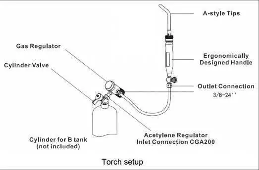
- The torch setup diagram illustrates the connection sequence: Cylinder -> Cylinder Valve -> Gas Regulator -> Hose -> Torch Handle -> A-style Tip.
Model compatibility
- Propane tips operate at 24 PSIG.
- MAPP tips operate at 42 PSIG.
- Acetylene tips operate at 15 PSIG.

Manual page author
Emily Carter
User documentation editor
Prepares concise manual descriptions and highlights the most useful setup, operation, and maintenance information for readers.