HVAC / Air Conditioners
User Manual for Viessmann 12XAK Floor Console Ductless System
Access the technical data and installation guide for the Viessmann 12XAK Floor Console Ductless System. This manual covers installation requirements, wiring diagrams, operating specifications, and maintenance procedures.
Table of contents
Manual images
Click an image to enlargeQuick guide from the manual
The Viessmann 12XAK is a floor-mounted, ductless indoor console unit designed for efficient heating and cooling. This manual provides technical data, installation guidelines, and wiring information. Key operational requirements include ensuring proper clearance for airflow, correct electrical wiring from the outdoor unit, and regular maintenance of the cleanable filters.
Product Overview
The system features microprocessor-based controls for comfort and efficiency. It includes an automatic air sweep for optimal air mixing, self-diagnostics for troubleshooting, and protection features such as freeze protection and high-temperature protection for the indoor coil.
Installation and Mounting
Proper installation is critical for system performance:
- Location: Position the unit on the floor against a wall. Ensure the return and discharge are not obstructed by furniture or curtains.
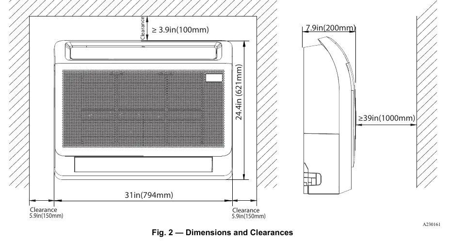
- Clearances: Maintain at least 3.9 inches (100mm) of clearance at the top and 5.9 inches (150mm) on the sides for proper airflow.
- Leveling: The unit must be level in all planes for reliable operation.
- Support: Ensure the mounting surface can support the weight of the fan coil.
Wiring and Connections
The system relies on specific wiring configurations:
- Power Supply: The indoor unit is powered directly from the outdoor unit.
- Wiring Type: Use 14/3 stranded wire with ground (600V insulation rating).
- Polarity: Wiring between the indoor and outdoor unit is polarity sensitive.
- Shielding: In high electromagnetic field (EMF) areas, use 14/2 stranded shielded wire for L2 and (S) connections, landing the shield on the ground in the outdoor unit only.
- Caution: Do not use BX wire. Ensure all connections are tight to prevent overheating.
Controls and Operation
The unit is operated via a wireless remote control (standard) or an optional wired remote controller. The system supports various modes, including Turbo, Silence, Sleep, and 46°F Heating Mode (Heating Setback).
Maintenance
To ensure longevity and efficiency:
- Filters: The unit is equipped with cleanable filters that should be maintained regularly.
- Coil Cleaning: The draw-thru design of the outdoor section allows for easier cleaning of coils.
- Diagnostics: The system includes self-diagnostics to assist in troubleshooting; error messages will appear on the unit.
Technical Specifications
- Voltage: 208/230V-1-60Hz.
- Airflow: 265 to 441 CFM depending on fan speed.
- Pipe Connections: Liquid: 1/4" (6.35mm); Suction: 1/2" (12.7mm).
- Operating Range: Cooling: 60-90°F (16-32°C); Heating: 32-86°F (0-30°C).
Manufacturer information
Viessmann Climate Solutions
Practical help
Common problems
Unit not cooling or heating effectively
Check for obstructions in front of the unit (furniture, curtains) that may cause air recirculation or short cycling.
Communication errors or wiring issues
Verify that wiring between the indoor and outdoor unit is polarity sensitive and that all connections are tight. Do not use BX wire.
Excessive noise or vibration
Ensure the unit is perfectly level and that interconnecting tubing is isolated from the building structure to prevent vibration transmission.
Before use
- Ensure the unit is mounted on the floor against a wall.
- Verify clearance: 3.9in (100mm) top, 5.9in (150mm) sides.
- Confirm power is supplied from the outdoor unit.
- Check that refrigerant lines are insulated with at least 1/2-in thick closed-cell insulation.
- Ensure filters are clean and properly seated.
Specs in practice
- Pipe Connection
- Liquid line: 1/4" (6.35mm); Suction line: 1/2" (12.7mm).
Images and diagrams
- Fig 2: Illustrates the required clearances for the unit to ensure proper airflow.
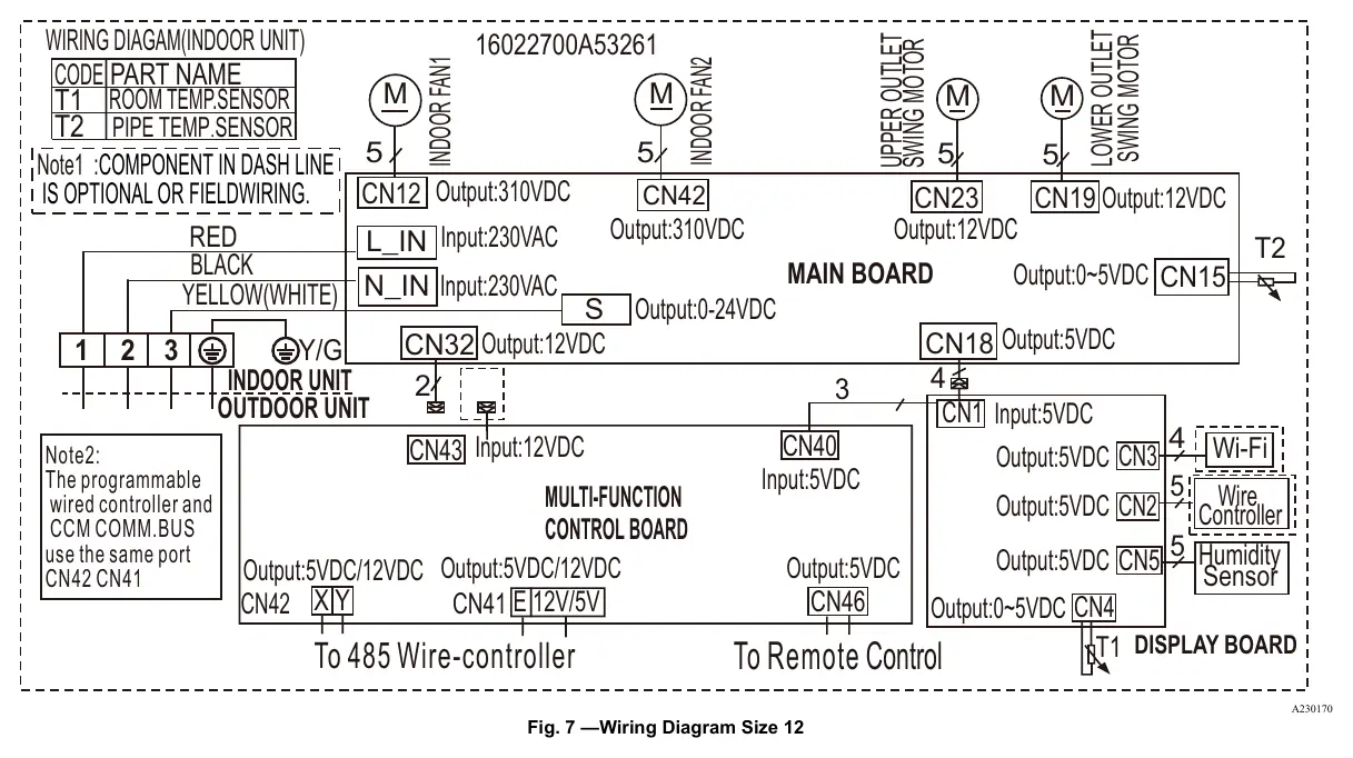
- Fig 7: Wiring diagram detailing connections for the main board, sensors, and motors.
Model compatibility
- Compatible with 38MA*R single zone and 38MGR multi-zone systems.
- Indoor unit is powered by the outdoor unit.

Manual page author
Emily Carter
User documentation editor
Prepares concise manual descriptions and highlights the most useful setup, operation, and maintenance information for readers.