HVAC / Air Conditioners
Installation Instructions for Viessmann VBC 130-A04.100 Control Unit
Professional installation guide for replacing the Viessmann VBC 130-A04.100 control unit. Includes safety procedures, compatibility, step-by-step replacement, coding address adjustments, and troubleshooting fault codes.
Table of contents
Manual images
Click an image to enlargeQuick guide from the manual
This document provides instructions for replacing the control unit on Vitodens boilers. Installation, initial start-up, inspection, maintenance, and repairs must only be carried out by a competent heating engineer or installation contractor.
Safety and Preparation
- Isolate power supply: Remove the mains fuse or use a mains isolator and safeguard against reconnection.
- Gas safety: Close the main gas shut-off valve and safeguard against reopening.
- Static protection: Before beginning work, touch earthed objects (e.g., heating or water pipes) to discharge static loads.
- Data backup: Before installation, call up and record the current values for coding addresses 82, 06, 28, 31, and 6F.
Replacement Procedure
Removing the old unit
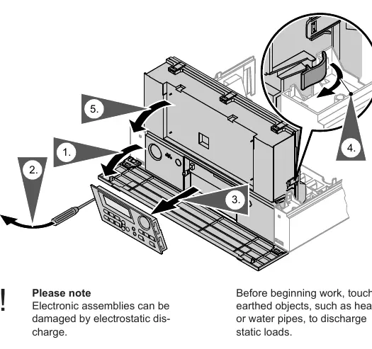
- Switch off the power supply.
- Remove the programming unit.
- Pivot the control unit down.
- Open the control unit enclosure.
- Undo the bayonet fitting and remove the pressure gauge.
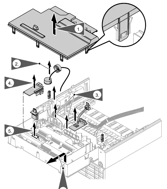
- Disconnect all plugs from the control unit.
- Remove existing extensions (H1, H2, LON, or cascade modules).
- Remove the boiler coding card.
- Release the locking tabs and remove the control unit.
Installing the new unit
- Insert the new control unit into the support and secure with locking tabs.
- Install extensions (H1, H2, LON, or cascade modules) into the new unit.
- Insert the boiler coding card into the new unit.
- Fit the pressure gauge and secure with the bayonet fitting.
- Re-insert all plugs into the control unit.
- Close the control unit enclosure and pivot it up.
- Insert the programming unit.
- Fit the front panel and start the boiler to check operation.
Adjusting the control unit
After installation, you may need to reset codes to factory settings:
- Press the L and G keys simultaneously for approx. 2 seconds.
- The display will show "Stand. setting? Yes".
- Press OK to confirm, or use the +/- keys to select "Stand. setting? No".
- Set the coding addresses as recorded previously.
Note: The gas type only needs to be converted for operation with LPG; the unit is set for natural gas by default.
Troubleshooting
The manual provides specific fault codes that may appear after replacing the control unit, including E1, E2, E3, E7, EA, and Eb. These generally relate to ionisation current issues, flow rate, or flame loss during calibration. Always check the ionisation electrode, flue system, and gas type allocation before pressing the reset button R.
Manufacturer information
Viessmann Climate Solutions
Practical help
Common problems
E1 / E7: Ionisation current issues
Check the gap between the ionisation electrode and burner gauze assembly. Inspect for electrode contamination and check plug-in connections.
E2: Flow switch shutdown
Ensure adequate heating water circulation volume. Check for scaling and blockages in the flow switch.
E3: Heat transfer too low
Ensure adequate heat transfer and check the temperature limiter.
EA: Ionisation current outside range
Check flue system for recirculation. If repeated resets fail, replace the boiler coding card.
Eb: Repeated flame loss
Check the gap between the ionisation electrode and burner gauze, verify gas type allocation, and check the flue system.
Before use
- Isolate the power supply.
- Close the main gas shut-off valve.
- Record existing coding addresses (82, 06, 28, 31, 6F).
- Touch earthed objects to discharge static electricity.
- Ensure you have original spare parts.
Specs in practice
- Coding address 16
- Sets the start point for cyclical calibration (30 °C to 127 °C).
- Coding address 17
- Sets the start point for urgent calibration (30 °C to 127 °C).
- Coding address 51
- Configures internal circulation pump logic for low loss headers or buffer cylinders.
Images and diagrams
- Page 3: Shows the sequence for removing the programming unit and pivoting the control unit down.
- Page 4: Illustrates the steps to open the enclosure, disconnect plugs, and remove the control unit.
Model compatibility
- Compatible with specific Vitodens boiler models listed in the application table on page 2.
- Requires original spare parts supplied or approved by Viessmann.

Manual page author
Emily Carter
User documentation editor
Prepares concise manual descriptions and highlights the most useful setup, operation, and maintenance information for readers.