HVAC / Heat Pumps
Installation and Service Guide for Viessmann Vitodens 111-W
Comprehensive installation and service guide for the Viessmann Vitodens 111-W gas condensing boiler. Includes mounting, electrical connections, commissioning, parameter settings, and troubleshooting fault codes.
Table of contents
Manual images
Click an image to enlargeImportant Information from the Manual
This document is intended exclusively for qualified contractors. It covers the installation, commissioning, maintenance, and troubleshooting of the Viessmann Vitodens 111-W wall-mounted gas condensing boiler. Always follow safety instructions to prevent accidents and material losses. Ensure the system is isolated from the power supply and the gas shut-off valve is closed before performing any work.
Product Description
The Vitodens 111-W is a gas condensing storage combi boiler featuring an Inox-Radial heat exchanger, a modulating MatriX-Plus burner, and an integrated stainless steel loading cylinder (46 l capacity). It is designed for sealed unvented heating systems.
Installation
Mounting: Fit the supplied pre-plumbing jig, mounting frame, or wall mounting bracket. Ensure the wall is suitable for the load. Connect all pipework so that it is free of load and torque stress.
Connections: Prepare water connections for heating flow, return, cold water, and DHW. Connect the condensate drain with a constant fall. Ensure the gas connection is sealed and checked for leaks.
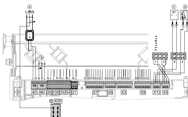
Electrical Connections: The appliance is delivered with a power cable. Connect to a 230 V, 50 Hz supply with a max 16 A fuse. Route extra low voltage (ELV) leads separately from 230 V cables.
Commissioning
Commissioning must be performed using the commissioning assistant. Key steps include:
- Filling the heating system and loading cylinder.
- Venting the heating system.
- Checking the gas type and performing a leak test on the balanced flue system.
- Setting parameters via the service menu.
System Configuration
Parameters can be adjusted via the service menu (b.2). This includes settings for flow temperature, pump operating modes, scald protection, and heating curves. Further settings are available via the ViGuide software tool.
Maintenance and Repairs
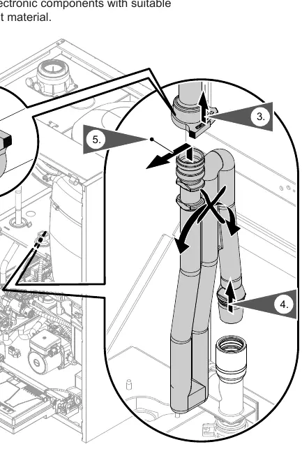
Regular maintenance is required to ensure safe operation. This includes cleaning the heating surfaces, checking the condensate drain and trap, and inspecting electrodes. Always use genuine Viessmann spare parts. For repairs, such as replacing the HBMU heat management unit or the plate heat exchanger, follow the specific procedures outlined in the manual.
Troubleshooting
The programming unit displays fault codes in the event of an error. Common fault codes include:
- 59, 457: Fan issues; check cables and power supply.
- 357: Insufficient gas supply; check gas pressure.
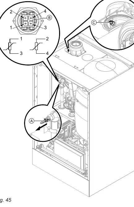
- 416: Flue gas temperature sensor incorrectly positioned.
- 74: System pressure too low; top up with water.
For detailed fault analysis, refer to the fault message table in the manual. If a fault persists, reset the appliance after the cause has been remedied.
Technical Data
The boiler is approved for installation in wet rooms in safety zone 3 (IP X1). It supports natural gas and LPG. Detailed specifications, including heating output ranges, power consumption, and dimensions, are provided in the specification section.
Manufacturer information
Viessmann Climate Solutions
Practical help
Common problems
Fault 59, 457
Check fan connecting cables and fan power supply.
Fault 357
Check gas supply pressure.
Fault 416
Flue gas temperature sensor incorrectly positioned. Reposition and reset.
Fault 74
System pressure too low. Top up with water and vent the system.
Before use
- Check wall condition for mounting
- Flush heating system thoroughly
- Ensure gas supply is connected and purged
- Fill trap with water before commissioning
- Check electrical connections for firm seating
Specs in practice
- Power supply
- 230 V, 50 Hz, max 16 A fuse
Images and diagrams
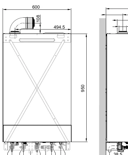
- Fig 1: Dimensions and connections
- Fig 12: Electrical connections
- Fig 27: Residual head of integral circulation pump
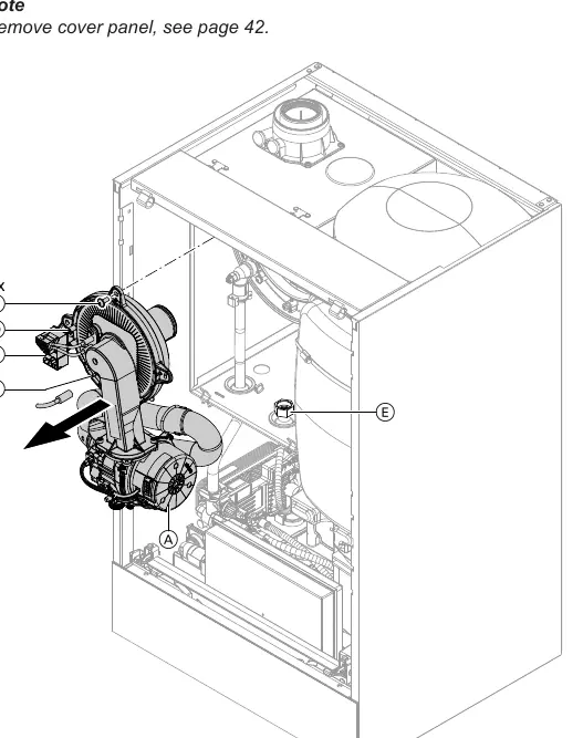
- Fig 30: Burner components
- Fig 59: Wiring diagram
Model compatibility
- Only for qualified contractors
- Requires specific flue systems (Skoberne or Groppalli)
- Multiple connection requires specific appliance types

Manual page author
Emily Carter
User documentation editor
Prepares concise manual descriptions and highlights the most useful setup, operation, and maintenance information for readers.